Sign In


E-Catalog > CHANDOX CHUCK > Pneumatic Chucks
Product Detail :
Pneumatic Chucks
RT
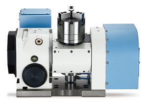
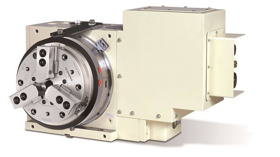
Rotary air chuck fixtures ( intermittent operation )
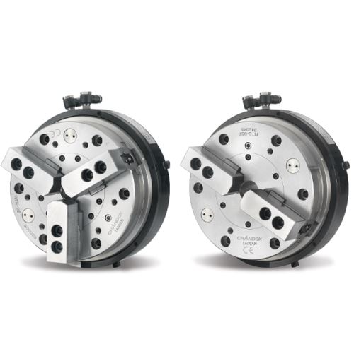
RTS,RTS-T
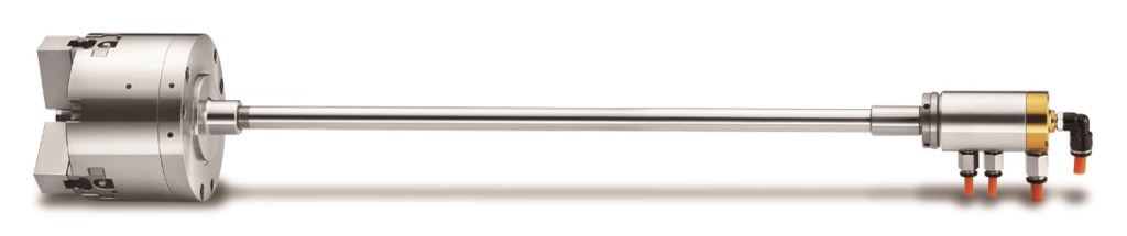
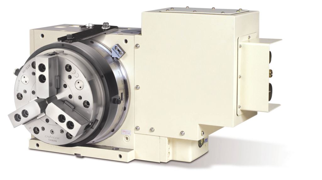
Rorary air chuck fixtures
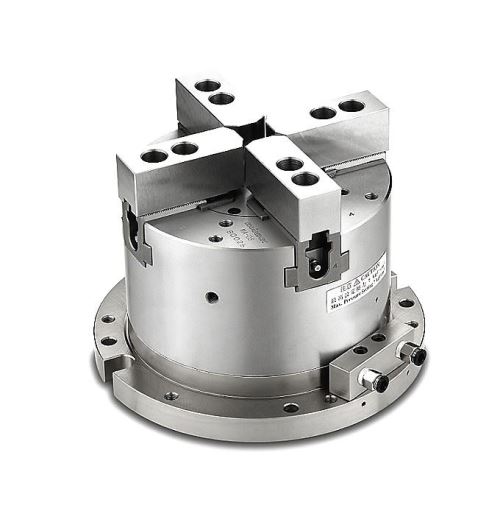
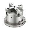
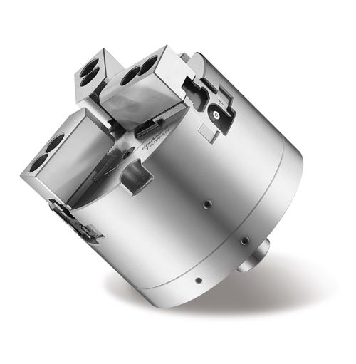
MA
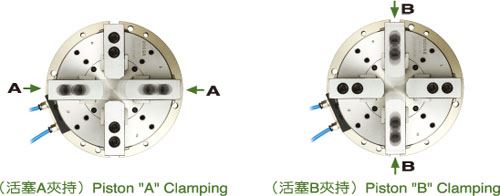
2 Actuating Axes Self-Centering Solid Air Chuck Fixtures
MR
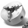
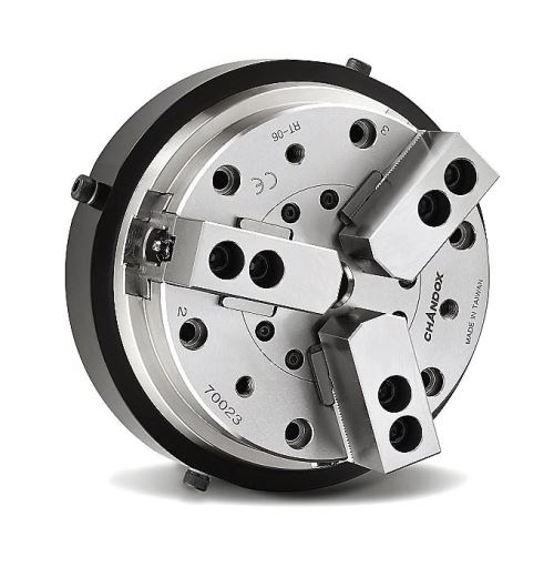
3-Jaw Air Chucks
MR
3-Jaw Air Chucks
DIMENSIONS

SPECIFICATIONS
UNIT/mm
| Inquiry | MODEL / SPEC | A | B | C | D | E | F | G | H | I | J | K | L | M |
|---|---|---|---|---|---|---|---|---|---|---|---|---|---|---|
 |
MR-04 | 117 | 60 | 24 | 25 | 3.5 | 84.5 | 26.7 | 49.5 | 14 | 10 | 23 | 5/8"-32UNF | 3-M8×1.25P(PCDø104) |
| MODEL / SPEC | Piston Area (cm2) | Plunger Stroke (mm) | Jaw Stroke [Diameter] (mm) | Gripping Force At Air Pressure 7kgf/cm2(0.7MPa) kgf(kN) | Max.Speed r.p.m(min-1) | Gripping Range |
|---|---|---|---|---|---|---|
| MR-04 | 57 | 9 | 3.8 | 1100(10.8) | 3800 | ø10~ø117 |
OPERATION EXAMPLE
MA
2 Actuating Axes Self-Centering Solid Air Chuck Fixtures
2 actuating axes self-centering solid air chuck fixtures is great for machining center. Two pairs of jaws clamp one after another to assure a workpiece to be locked completely.
1.Rust-proof for Pneumatic Cylinder:Inside wall of cylinder being rustproof treated; cylinder can work under wet or high moisture circumstances without rusty or seized trouble.
2.Dusts-proof and Waterproof:Dust-proof and Waterproof structure prevents work-chips and coolant water from entering into inside of chuck cylinder to maintain its accuracy and lead to longer service life.
3.4-jaw Clamping and Self-centering:4-jaw clamping are steadier for machining. Two pairs of jaws are moved independently to assure complete lock and self-centering.
DIMENSIONS

SPECIFICATIONS
UNIT/mm
| Inquiry | MODEL / SPEC | A | B | D | E | F | G | H | I | J | K | L |
|---|---|---|---|---|---|---|---|---|---|---|---|---|
|
|
MA-06 | 224 | 175 | 20 | 130 | 170 | 40 | 73 | 20 | 12 | 31 | 18 |
|
|
MA-08 | 265 | 210 | 22 | 154 | 196 | 42 | 95 | 25 | 14 | 35 | 18 |
|
|
MA-10 | 315 | 250 | 25 | 176 | 222 | 46 | 110 | 30 | 16 | 40 | 18 |
| MODEL / SPEC | M | O | P | Q |
|---|---|---|---|---|
| MA-06 | ø11(PCDø202) | M10×1.5P(PCDø202) | 4-M8×1.25P(PCDø124) | 4-M8×1.25P(PCDø156) |
| MA-08 | ø11(PCDø243) | M10×1.5P(PCDø243) | 4-M10×1.5P(PCDø140) | 4-M10×1.5P(PCDø186) |
| MA-10 | ø13(PCDø285) | M12×1.75P(PCDø285) | 4-M10×1.5P(PCDø176) | 4-M10×1.5P(PCDø224) |
| MODEL / SPEC | A Piston Area Push Side (cm2) | A Piston Area Pull Side (cm2) | B Piston Area Push Side (cm2) | B Piston Area Pull Side (cm2) | Plunger Stroke (mm) | Jaw Stroke [Diameter] (mm) | Gripping Force At Air Pressure 7kgf/cm2(0.7MPa) kgf(kN) | Weight (kg) | Gripping Range |
|---|---|---|---|---|---|---|---|---|---|
| MA-06 | 127 | 108 | 122 | 117 | 12 | 5.5 | 4500(44) | 24.8 | ø25~ø175 |
| MA-08 | 184 | 157 | 176 | 169 | 16 | 7.4 | 6400(63) | 41.3 | ø30~ø210 |
| MA-10 | 270 | 239 | 254 | 241 | 19 | 8.8 | 9500(93) | 65.6 | ø35~ø250 |
OPERATION EXAMPLE
RTS,RTS-T
Rorary air chuck fixtures
LOW TORQUE、BULIT-IN CHECK VALVE CONTINUOUS ROTATING
1.When The Chuck is Rotating Continuously: Higher rotation speed to fit with more kind of working, the rotating speed has to be within the max speed limit.
2.Built-in Check Valve: Design with built-in Check Valve. It's doesn't need to supply the air continuously and remain low working torque also reduce the air consumption.
3.Dustproof and Drainage Patent Structure: This can prevent the metal chips and coolant get into the chuck inside while processing, and maintain.
4.Integral Pneumatic Cylinder: Connect chuck and built-in cylinder to each other directly; thus enables operation stability. Moreover, it is more convenient for installation and operation since the use of a drawtube and drawbar are no longer necessary.
5.Rustproof Treated Cylinder: The cylinder won't get rusty and seized even wet or high moisture working environment.
DIMENSIONS

SPECIFICATIONS
UNIT/mm
| Inquiry | MODEL / SPEC | A | B | C | D | E | F | G | H | I | J | K |
|---|---|---|---|---|---|---|---|---|---|---|---|---|
|
|
RTS-05 | 140 | 85 | 16 | 60 | 6 | 182 | 33.6 | 62 | 14 | 10 | 25 |
|
|
RTS-06 | 170 | 93 | 20 | 80 | 7 | 215 | 40.4 | 73 | 20 | 12 | 31 |
|
|
RTS-08 | 215 | 112 | 30 | 110 | 8 | 255 | 42.4 | 95 | 25 | 14 | 35 |
|
|
RTS-10 | 255 | 120 | 43 | 140 | 8 | 300 | 46.4 | 110 | 30 | 16 | 40 |
|
|
RTS-05T | 140 | 85 | 16 | 60 | 6 | 182 | 33.6 | 62 | 14 | 10 | 25 |
|
|
RTS-06T | 170 | 93 | 20 | 80 | 7 | 215 | 40.4 | 73 | 20 | 12 | 31 |
| MODEL / SPEC | L | M | N max. | N min. | O max. | O min. | P | R |
|---|---|---|---|---|---|---|---|---|
| RTS-05 | 6-M8×1.25P | PCDø118 | 26.93 | 24.62 | 20.05 | 6.55 | 18.5 | 6-M6×1P(PCDø92) |
| RTS-06 | 6-M8×1.25P | PCDø147 | 36.46 | 33.69 | 21.55 | 15.55 | 18.5 | 6-M8×1.25P(PCDø120) |
| RTS-08 | 6-M10×1.5P | PCDø185 | 44.92 | 41.52 | 29.55 | 17.55 | 19.5 | 6-M10×1.5P(PCDø155) |
| RTS-10 | 6-M10×1.5P | PCDø220 | 53.63 | 49.59 | 36.55 | 17.05 | 21.5 | 6-M12×1.75P(PCDø190) |
| RTS-05T | 6-M8×1.25P | PCDø118 | 26.93 | 24.62 | 20.05 | 6.55 | 18.5 | 2-M6×1P(PCDø92) |
| RTS-06T | 6-M8×1.25P | PCDø147 | 36.46 | 33.69 | 21.55 | 15.55 | 18.5 | 2-M8×1.25P(PCDø115) |
| MODEL / SPEC | Thru-Hole [Diameter] (mm) | Piston Area (cm2) | Plunger Stroke (mm) | Jaw Stroke [Diameter] (mm) | Max.Speed r.p.m(min-1) | Pressure Setting Range kgf/cm2(MPa) | Gripping Force At Air Pressure 7kgf/cm2(0.7MPa) kgf(kN) | Gripping Range | Weight (kg) |
|---|---|---|---|---|---|---|---|---|---|
| RTS-05 | 16 | 74 | 10 | 4.6 |
450
|
2-7(0.2-0.7) | 1340(13.1) | ø4~ø136 | 10 |
| RTS-06 | 20 | 120 | 13 | 5.5 |
350
|
2-7(0.2-0.7) | 2330(22.8) | ø25~ø166 | 16.8 |
| RTS-08 | 30 | 190 | 16 | 6.8 |
300
|
2-7(0.2-0.7) | 3730(36.5) | ø33~ø215 | 30.6 |
| RTS-10 | 43 | 280 | 19 | 8.0 |
250
|
2-7(0.2-0.7) | 5480(53.7) | ø43~ø255 | 45.1 |
| RTS-05T | 16 | 74 | 10 | 4.6 |
450
|
2-7(0.2-0.7) | 1340(13.1) | ø4~ø136 | 9.7 |
| RTS-06T | 20 | 120 | 13 | 5.5 |
350
|
2-7(0.2-0.7) | 2330(22.8) | ø25~ø166 | 16.3 |
OPERATION EXAMPLE
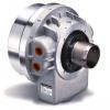
RT
Rotary air chuck fixtures ( intermittent operation )
INTERMITTENT OPERATION
Suitable for light cutting
It's ldeal for dividing or cutting work pieces by mounting the chuck on indexing table or rotary table. The distinctive feature is that chuck rotates with the spindle of indexing table or rotary table.
1.The chuck is designed for intermittently rotate in limited rotary speed with rotary table.
2.Rustproof treated cylinder : The cylinder won't get rusty and seized even in wet or hign moisture working environment.
3.Integral pneumatic cylinder :Connect chuck and built-in cylinder to each other directly;thus enables operation stability.Moreover,it is more convenient for installation and operation since the use of draw tube and draw bar are no longer necessary.
DIMENSIONS
")
SPECIFICATIONS
UNIT/mm
| Inquiry | MODEL / SPEC | A | B | C | D | E | F | G | H | I | J | K |
|---|---|---|---|---|---|---|---|---|---|---|---|---|
|
|
RT-05 | 140 | 85 | 16 | 60 | 6 | 182 | 33.6 | 62 | 14 | 10 | 25 |
|
|
RT-06 | 170 | 93 | 20 | 80 | 7 | 215 | 40.4 | 73 | 20 | 12 | 31 |
|
|
RT-08 | 215 | 112 | 30 | 110 | 8 | 255 | 42.4 | 95 | 25 | 14 | 35 |
| MODEL / SPEC | L | M | N max. | N min. | O max. | O min. | P | Q | R |
|---|---|---|---|---|---|---|---|---|---|
| RT-05 | 6-M8×1.25P | PCDø118 | 26.93 | 24.62 | 20.05 | 6.55 | 26 | -- | 3-M8×1.25P (PCDø92) |
| RT-06 | 6-M8×1.25P | PCDø147 | 36.46 | 33.69 | 21.55 | 15.55 | 26 | -- | 3-M10×1.5P (PCDø130) |
| RT-08 | 6-M10×1.5P | PCDø185 | 44.92 | 41.52 | 29.55 | 17.55 | 27 | 3-M10×1.5P (PCDø186) | 3-M10×1.5P (PCDø146) |
| MODEL / SPEC | Thru-Hole [Diameter] (mm) | Piston Area (cm2) | Plunger Stroke (mm) | Jaw Stroke [Diameter] (mm) | Max.Speed r.p.m(min-1) | Max Hydr. Pressure kgf/cm2 (MPa) | Gripping Force At Air Pressure 7kgf/cm2(0.7MPa) kgf(kN) | Gripping Range |
|---|---|---|---|---|---|---|---|---|
| RT-05 | 16 | 74 | 10 | 4.6 | 51 | 7(0.7) | 1340(13.1) | ø4~ø140 |
| RT-06 | 20 | 120 | 13 | 5.5 | 41 | 7(0.7) | 2330(22.8) | ø25~ø170 |
| RT-08 | 30 | 190 | 16 | 6.8 | 33 | 7(0.7) | 3730(36.5) | ø33~ø215 |
OPERATION EXAMPLE
MR
3-Jaw Air Chucks
DIMENSIONS
SPECIFICATIONS
UNIT/mm
| Inquiry | MODEL / SPEC | A | B | C | D | E | F | G | H | I | J | K | L | M |
|---|---|---|---|---|---|---|---|---|---|---|---|---|---|---|
|
|
MR-04 | 117 | 60 | 24 | 25 | 3.5 | 84.5 | 26.7 | 49.5 | 14 | 10 | 23 | 5/8"-32UNF | 3-M8×1.25P(PCDø104) |
| MODEL / SPEC | Piston Area (cm2) | Plunger Stroke (mm) | Jaw Stroke [Diameter] (mm) | Gripping Force At Air Pressure 7kgf/cm2(0.7MPa) kgf(kN) | Max.Speed r.p.m(min-1) | Gripping Range |
|---|---|---|---|---|---|---|
| MR-04 | 57 | 9 | 3.8 | 1100(10.8) | 3800 | ø10~ø117 |
OPERATION EXAMPLE
MA
2 Actuating Axes Self-Centering Solid Air Chuck Fixtures
2 actuating axes self-centering solid air chuck fixtures is great for machining center. Two pairs of jaws clamp one after another to assure a workpiece to be locked completely.
1.Rust-proof for Pneumatic Cylinder:Inside wall of cylinder being rustproof treated; cylinder can work under wet or high moisture circumstances without rusty or seized trouble.
2.Dusts-proof and Waterproof:Dust-proof and Waterproof structure prevents work-chips and coolant water from entering into inside of chuck cylinder to maintain its accuracy and lead to longer service life.
3.4-jaw Clamping and Self-centering:4-jaw clamping are steadier for machining. Two pairs of jaws are moved independently to assure complete lock and self-centering.
1.Rust-proof for Pneumatic Cylinder:Inside wall of cylinder being rustproof treated; cylinder can work under wet or high moisture circumstances without rusty or seized trouble.
2.Dusts-proof and Waterproof:Dust-proof and Waterproof structure prevents work-chips and coolant water from entering into inside of chuck cylinder to maintain its accuracy and lead to longer service life.
3.4-jaw Clamping and Self-centering:4-jaw clamping are steadier for machining. Two pairs of jaws are moved independently to assure complete lock and self-centering.
DIMENSIONS
SPECIFICATIONS
UNIT/mm
| Inquiry | MODEL / SPEC | A | B | D | E | F | G | H | I | J | K | L |
|---|---|---|---|---|---|---|---|---|---|---|---|---|
|
|
MA-06 | 224 | 175 | 20 | 130 | 170 | 40 | 73 | 20 | 12 | 31 | 18 |
|
|
MA-08 | 265 | 210 | 22 | 154 | 196 | 42 | 95 | 25 | 14 | 35 | 18 |
|
|
MA-10 | 315 | 250 | 25 | 176 | 222 | 46 | 110 | 30 | 16 | 40 | 18 |
| MODEL / SPEC | M | O | P | Q |
|---|---|---|---|---|
| MA-06 | ø11(PCDø202) | M10×1.5P(PCDø202) | 4-M8×1.25P(PCDø124) | 4-M8×1.25P(PCDø156) |
| MA-08 | ø11(PCDø243) | M10×1.5P(PCDø243) | 4-M10×1.5P(PCDø140) | 4-M10×1.5P(PCDø186) |
| MA-10 | ø13(PCDø285) | M12×1.75P(PCDø285) | 4-M10×1.5P(PCDø176) | 4-M10×1.5P(PCDø224) |
| MODEL / SPEC | A Piston Area Push Side (cm2) | A Piston Area Pull Side (cm2) | B Piston Area Push Side (cm2) | B Piston Area Pull Side (cm2) | Plunger Stroke (mm) | Jaw Stroke [Diameter] (mm) | Gripping Force At Air Pressure 7kgf/cm2(0.7MPa) kgf(kN) | Weight (kg) | Gripping Range |
|---|---|---|---|---|---|---|---|---|---|
| MA-06 | 127 | 108 | 122 | 117 | 12 | 5.5 | 4500(44) | 24.8 | ø25~ø175 |
| MA-08 | 184 | 157 | 176 | 169 | 16 | 7.4 | 6400(63) | 41.3 | ø30~ø210 |
| MA-10 | 270 | 239 | 254 | 241 | 19 | 8.8 | 9500(93) | 65.6 | ø35~ø250 |
OPERATION EXAMPLE
RTS,RTS-T
Rorary air chuck fixtures
LOW TORQUE、BULIT-IN CHECK VALVE CONTINUOUS ROTATING
1.When The Chuck is Rotating Continuously: Higher rotation speed to fit with more kind of working, the rotating speed has to be within the max speed limit.
2.Built-in Check Valve: Design with built-in Check Valve. It's doesn't need to supply the air continuously and remain low working torque also reduce the air consumption.
3.Dustproof and Drainage Patent Structure: This can prevent the metal chips and coolant get into the chuck inside while processing, and maintain.
4.Integral Pneumatic Cylinder: Connect chuck and built-in cylinder to each other directly; thus enables operation stability. Moreover, it is more convenient for installation and operation since the use of a drawtube and drawbar are no longer necessary.
5.Rustproof Treated Cylinder: The cylinder won't get rusty and seized even wet or high moisture working environment.
1.When The Chuck is Rotating Continuously: Higher rotation speed to fit with more kind of working, the rotating speed has to be within the max speed limit.
2.Built-in Check Valve: Design with built-in Check Valve. It's doesn't need to supply the air continuously and remain low working torque also reduce the air consumption.
3.Dustproof and Drainage Patent Structure: This can prevent the metal chips and coolant get into the chuck inside while processing, and maintain.
4.Integral Pneumatic Cylinder: Connect chuck and built-in cylinder to each other directly; thus enables operation stability. Moreover, it is more convenient for installation and operation since the use of a drawtube and drawbar are no longer necessary.
5.Rustproof Treated Cylinder: The cylinder won't get rusty and seized even wet or high moisture working environment.
DIMENSIONS
SPECIFICATIONS
UNIT/mm
| Inquiry | MODEL / SPEC | A | B | C | D | E | F | G | H | I | J | K |
|---|---|---|---|---|---|---|---|---|---|---|---|---|
|
|
RTS-05 | 140 | 85 | 16 | 60 | 6 | 182 | 33.6 | 62 | 14 | 10 | 25 |
|
|
RTS-06 | 170 | 93 | 20 | 80 | 7 | 215 | 40.4 | 73 | 20 | 12 | 31 |
|
|
RTS-08 | 215 | 112 | 30 | 110 | 8 | 255 | 42.4 | 95 | 25 | 14 | 35 |
|
|
RTS-10 | 255 | 120 | 43 | 140 | 8 | 300 | 46.4 | 110 | 30 | 16 | 40 |
|
|
RTS-05T | 140 | 85 | 16 | 60 | 6 | 182 | 33.6 | 62 | 14 | 10 | 25 |
|
|
RTS-06T | 170 | 93 | 20 | 80 | 7 | 215 | 40.4 | 73 | 20 | 12 | 31 |
| MODEL / SPEC | L | M | N max. | N min. | O max. | O min. | P | R |
|---|---|---|---|---|---|---|---|---|
| RTS-05 | 6-M8×1.25P | PCDø118 | 26.93 | 24.62 | 20.05 | 6.55 | 18.5 | 6-M6×1P(PCDø92) |
| RTS-06 | 6-M8×1.25P | PCDø147 | 36.46 | 33.69 | 21.55 | 15.55 | 18.5 | 6-M8×1.25P(PCDø120) |
| RTS-08 | 6-M10×1.5P | PCDø185 | 44.92 | 41.52 | 29.55 | 17.55 | 19.5 | 6-M10×1.5P(PCDø155) |
| RTS-10 | 6-M10×1.5P | PCDø220 | 53.63 | 49.59 | 36.55 | 17.05 | 21.5 | 6-M12×1.75P(PCDø190) |
| RTS-05T | 6-M8×1.25P | PCDø118 | 26.93 | 24.62 | 20.05 | 6.55 | 18.5 | 2-M6×1P(PCDø92) |
| RTS-06T | 6-M8×1.25P | PCDø147 | 36.46 | 33.69 | 21.55 | 15.55 | 18.5 | 2-M8×1.25P(PCDø115) |
| MODEL / SPEC | Thru-Hole [Diameter] (mm) | Piston Area (cm2) | Plunger Stroke (mm) | Jaw Stroke [Diameter] (mm) | Max.Speed r.p.m(min-1) | Pressure Setting Range kgf/cm2(MPa) | Gripping Force At Air Pressure 7kgf/cm2(0.7MPa) kgf(kN) | Gripping Range | Weight (kg) |
|---|---|---|---|---|---|---|---|---|---|
| RTS-05 | 16 | 74 | 10 | 4.6 | 450 | 2-7(0.2-0.7) | 1340(13.1) | ø4~ø136 | 10 |
| RTS-06 | 20 | 120 | 13 | 5.5 | 350 | 2-7(0.2-0.7) | 2330(22.8) | ø25~ø166 | 16.8 |
| RTS-08 | 30 | 190 | 16 | 6.8 | 300 | 2-7(0.2-0.7) | 3730(36.5) | ø33~ø215 | 30.6 |
| RTS-10 | 43 | 280 | 19 | 8.0 | 250 | 2-7(0.2-0.7) | 5480(53.7) | ø43~ø255 | 45.1 |
| RTS-05T | 16 | 74 | 10 | 4.6 | 450 | 2-7(0.2-0.7) | 1340(13.1) | ø4~ø136 | 9.7 |
| RTS-06T | 20 | 120 | 13 | 5.5 | 350 | 2-7(0.2-0.7) | 2330(22.8) | ø25~ø166 | 16.3 |
OPERATION EXAMPLE
RT
Rotary air chuck fixtures ( intermittent operation )
INTERMITTENT OPERATION
Suitable for light cutting
It's ldeal for dividing or cutting work pieces by mounting the chuck on indexing table or rotary table. The distinctive feature is that chuck rotates with the spindle of indexing table or rotary table.
1.The chuck is designed for intermittently rotate in limited rotary speed with rotary table.
2.Rustproof treated cylinder : The cylinder won't get rusty and seized even in wet or hign moisture working environment.
3.Integral pneumatic cylinder :Connect chuck and built-in cylinder to each other directly;thus enables operation stability.Moreover,it is more convenient for installation and operation since the use of draw tube and draw bar are no longer necessary.
Suitable for light cutting
It's ldeal for dividing or cutting work pieces by mounting the chuck on indexing table or rotary table. The distinctive feature is that chuck rotates with the spindle of indexing table or rotary table.
1.The chuck is designed for intermittently rotate in limited rotary speed with rotary table.
2.Rustproof treated cylinder : The cylinder won't get rusty and seized even in wet or hign moisture working environment.
3.Integral pneumatic cylinder :Connect chuck and built-in cylinder to each other directly;thus enables operation stability.Moreover,it is more convenient for installation and operation since the use of draw tube and draw bar are no longer necessary.
DIMENSIONS
SPECIFICATIONS
UNIT/mm
| Inquiry | MODEL / SPEC | A | B | C | D | E | F | G | H | I | J | K |
|---|---|---|---|---|---|---|---|---|---|---|---|---|
|
|
RT-05 | 140 | 85 | 16 | 60 | 6 | 182 | 33.6 | 62 | 14 | 10 | 25 |
|
|
RT-06 | 170 | 93 | 20 | 80 | 7 | 215 | 40.4 | 73 | 20 | 12 | 31 |
|
|
RT-08 | 215 | 112 | 30 | 110 | 8 | 255 | 42.4 | 95 | 25 | 14 | 35 |
| MODEL / SPEC | L | M | N max. | N min. | O max. | O min. | P | Q | R |
|---|---|---|---|---|---|---|---|---|---|
| RT-05 | 6-M8×1.25P | PCDø118 | 26.93 | 24.62 | 20.05 | 6.55 | 26 | -- | 3-M8×1.25P (PCDø92) |
| RT-06 | 6-M8×1.25P | PCDø147 | 36.46 | 33.69 | 21.55 | 15.55 | 26 | -- | 3-M10×1.5P (PCDø130) |
| RT-08 | 6-M10×1.5P | PCDø185 | 44.92 | 41.52 | 29.55 | 17.55 | 27 | 3-M10×1.5P (PCDø186) | 3-M10×1.5P (PCDø146) |
| MODEL / SPEC | Thru-Hole [Diameter] (mm) | Piston Area (cm2) | Plunger Stroke (mm) | Jaw Stroke [Diameter] (mm) | Max.Speed r.p.m(min-1) | Max Hydr. Pressure kgf/cm2 (MPa) | Gripping Force At Air Pressure 7kgf/cm2(0.7MPa) kgf(kN) | Gripping Range |
|---|---|---|---|---|---|---|---|---|
| RT-05 | 16 | 74 | 10 | 4.6 | 51 | 7(0.7) | 1340(13.1) | ø4~ø140 |
| RT-06 | 20 | 120 | 13 | 5.5 | 41 | 7(0.7) | 2330(22.8) | ø25~ø170 |
| RT-08 | 30 | 190 | 16 | 6.8 | 33 | 7(0.7) | 3730(36.5) | ø33~ø215 |
OPERATION EXAMPLE