  |
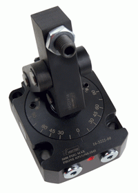
Overview:
- Engineered with tapered roller bearings for increased durability.
- Enhanced efficiency with reduced passage restrictions.
- Increased operational speeds.
- Simplified manifold mounting.
- Interchangeable mounting between all sizes.
- Used units are fully factory refurbishable.
- Accomodates electrical slip rings.
- SR6: Slip ring, 6 circuit
- SR12: Slip ring, 12 circuit
Operating Parameter Guidelines:
- Operating Temperature Range: 40-160 F°.
- Max RPM / Max Torque table.
- Torque requirements may vary depending on port configuration and pressure run through ports. Testing of your specific application may be required.
- Air may be run in any available passage.
- Rotating<
Cylinder Standard Features
- Most common and least expensive form of hydraulic clamping
- Adjustable force ranging from "minimal" to maximum cylinder capacity, by adjusting the input pressure
- Designed for long life in high production applications. Don't gamble with "cheap" cylinders which wear out prematurely
|

|
BHC™ (Black Hard Coating) on the cylinder bodies helps prevent scoring and scratching. After years of use, cylinder removal is easier because the BHC™ corrosion resistance is better than black oxide or chrome plating.
Proprietary seal designs reduce leakage and increase seal life for longer lasting, dependable cylinders.
Threaded models use positionable, SAE 4 fluid ports.
Manifold models supplied with gasket to seal against the cavity bottom.
Hardened chrome alloy steel pistons won't "mushroom" even when used without grippers.
Special wipers keep chips and contaminants out.
Positive piston stop shoulder keeps the spring from "bottoming out" guarding against premature spring failure which can plague other cylinder brands.
Block Body Pull Cylinders
| This advanced design block body cylinder mounts under the surface plate to pull a threaded fastener, making for easy-to-build fixturing on the new designs and giving you the option to add hydraulic control to many existing fixtures SAE porting receives fittings for either flexible or hard tubing external plumbing. |
 |
-
Ramp feature helps keep chips from packing
and coolant contaminants from entering the cylinder.
-
Save hours by not manual clamping.
-
Automate your new or existing fixtures that use
wedge driven or bolt down clamps.
-
Available in nine plunger thread and capacity
combinations designed to fit Mitee-Bite Uniforce,
Pitbull, ID Xpansion and OK Vise clamps.
-
Short stroke lengths make for a more compact device.
-
Easily plumbed using either flexible hose or hard tubing.
-
Two SAE ports per cylinder to easily connect
multiple devices.
|

|
Model
No.
|
Cylinder Capacity*
Retract
|
Stroke**
|
Plunger Thread***
|
Body Height
|
Effective Piston Area (sq. in.)
Retract
|
Oil Capacity
(cu. in.)
Retract
|
|---|
| 20-1106-01 |
980 |
.13 |
8-32 |
1.59 |
.20 |
.03 |
| 20-1109-01 |
2000 |
.19 |
1/4-20 |
1.83 |
.40 |
.10 |
| 20-1111-00 |
2950 |
.19 |
1/4-20 |
1.98 |
.59 |
.14 |
| 20-1111-01 |
2950 |
.19 |
5/16-18 |
1.98 |
.59 |
.14 |
| 20-1113-00 |
5200 |
.19 |
3/8-16 |
2.10 |
1.04 |
.25 |
| 20-1113-01 |
5200 |
.19 |
1/2-13 |
2.10 |
1.04 |
.25 |
| 20-1116-00 |
9000 |
.31 |
1/2-13 |
2.63 |
1.80 |
.60 |
| 20-1116-01 |
9000 |
.31 |
5/8-11 |
2.63 |
1.80 |
.60 |
| 20-1121-00 |
17100 |
.31 |
5/8-11 |
2.94 |
3.54 |
1.23 |
|
Single Acting (S/A) Cylinders actuated hydraulically in one direction, spring returned
|
*Cylinder capacities are listed at 5000 PSI operating pressure. The minimum operating pressure is 500 PSI for D/A operation and 750 PSI for S/A operation. The cylinder force is adjustable by varying the hydraulic pressure to the cylinder. To determine the approximate output of the cylinder for your application, divide the cylinder capacity shown above by 5000 PSI, and multiply the resultant by your system pressure in PSI to obtain the approximate cylinder force for your application. (Actual forces will vary slightly due to internal friction and/or return spring force.)
**Cylinder stroke may exceed stroke of clamping element. Limiting cylinder stroke may be required to ensure proper operation of clamping element.
*** At full cylinder capacity, fastener life will be limited and fasteners should be considered service items. Fasteners should be replaced frequently when operating at full capacity to prevent plunger damage. Models 20-1111-00 and 20-1113-00 are not recommended for use above 2500 PSI.
|
Threaded Mini-Cylinders
Specifications
** Cylinder capacities are listed at 5,000 psi maximum operating pressure. The output force is adjustable by varying hydraulic system pressure. To determine approximate output force for your application, multiply the Piston Area X Your System Operating Pressure (Actual force may vary slightly due to friction loss, wiper drag and/or return springs.)
Threaded Cylinders
Specifications
Block Cylinders
Specifications
 |
 |
|
|
|
** Cylinder capacities are listed at 5000 psi maximum operating pressure. The output force is adjustable by varying the hydraulic system pressure. To determine the approximate output force for your application, multiply the piston area x your system operating pressure. (Actual force may vary slightly due to friction loss, seal and wiper drag, and/or return springs.)
|
Manifold Mount Block Cylinders
Specifications
Hollow Rod Cylinders (Through Hole, center pull)
Specifications
 |
 |
| Model No. | Cylinder
Capacity
(lb.)** | Hydraulic
Connection | Stroke
(in.) | Body
Size | Minimum
Height
(in.) | Piston
Area
(sq. in.) | Oil
Capacity
(cu. in.) |
|---|
| 20-2113-03 |
4600 |
SAE |
0.25 |
2.16 X 1.63 X 1.72
|
2.00 |
0.920 |
0.230 |
| 21-2113-03 |
SAE and MM |
| 20-2115-04 |
6600 |
SAE |
0.38 |
2.44 X 1.95 X 2.22
|
2.50 |
1.325 |
0.500 |
| 21-2115-04 |
SAE and MM |
| 20-2120-05 |
11700 |
SAE |
0.50 |
2.99 X 2.54 X 2.59
|
3.00 |
2.356 |
1.178 |
| 21-2120-05 |
SAE and MM |
| 20-2213-03 |
4600 |
SAE |
0.25 |
2.16 X 1.63 X 1.72
|
2.00 |
0.920 |
0.230 |
| 20-2215-04 |
6600 |
SAE |
0.38 |
2.44 X 1.95 X 2.22
|
2.50 |
1.325 |
0.500 |
| 20-2220-05 |
11700 |
SAE |
0.50 |
2.99 X 2.54 X 2.59
|
3.00 |
2.356 |
1.178 |
|
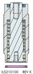
Cartridge Mount Mini-Cylinders
Specifications
 |
 |
| Model No*. | Cylinder
Capacity
(lb.)** | Stroke
(in.) | Body Thread | Minimum
Length
(in.) | Piston Area
(sq.in.) | Oil Capacity
(cu.in.) |
|---|
| Single Acting (S/A) Cylinders, actuated hydraulically 1 direction, spring returned. |
| 21-0102-00 |
125 |
0.12 |
3/8-24 |
1.16 |
0.028 |
0.004 |
| 21-0104-02 |
550 |
0.20 |
5/8-18
|
1.14
|
0.110
|
0.021
|
| 21-0105-03 |
980 |
0.25 |
3/4-16
|
1.48
|
0.196
|
0.049
|
| 21-0105-04 |
1.44
|
| 21-0105-05 |
0.50 |
1.83
|
0.098
|
| 21-0105-06 |
1.83
|
| 21-0108-04 |
2200 |
0.38 |
1 1/16 - 16 |
1.36
|
0.442 |
0.166
|
| 21-0108-05 |
1.32
|
| 21-0108-08 |
0.75 |
2.43 |
0.332 |
| 21-0110-04 |
3900 |
0.31 |
1 5/16 - 16 |
1.47 |
0.785 |
0.243 |
| 21-0110-05 |
3900 |
0.50 |
1 5/16 - 16 |
1.66 |
0.785 |
0.394 |
|
Cartridge Mount Push/Pull Cylinder
 |
 |
Model No.
**** | Cylinder
Capacity*
(lbs | Stroke** (in.) | Plunger***
Thread | Minimum Length (in.) | Effective Piston Area (sq.in.)
| Oil Capacity (cu.in.) | Oil Capacity (cu.in.) |
|---|
| Extend | Retract | Extend | Retract | Extend | Retract |
|---|
| 21-0206-00 |
1500 |
980 |
0.25 |
6-32 |
1.44 |
0.31 |
0.20 |
0.08 |
0.05 |
| 21-0206-01 |
8-32 |
| 21-0209-00 |
2900 |
2000 |
0.25 |
8-32 |
1.44 |
0.60 |
0.40 |
0.15 |
0.10 |
| 21-0209-01 |
1/4 - 20 |
| 21-0210-00 |
3900 |
2950 |
0.25 |
1/4 - 20 |
1.59 |
0.79 |
0.59 |
0.20 |
0.15 |
| 21-0210-01 |
5/16 - 18 |
| 21-0213-00 |
7400 |
5200 |
0.25 |
3/8 - 16 |
1.59 |
1.48 |
1.04 |
0.37 |
0.26 |
| 21-0213-01 |
1/2 -13
|
| 21-0216-00 |
12000 |
9000 |
0.38 |
1/2 - 13 |
1.88 |
2.41 |
1.80 |
0.90 |
0.68 |
| 21-0216-01 |
5/8 - 11 |
2.13 |
| 21-0221-00 |
22000 |
17100 |
0.38
|
5/8 - 11 |
2.13 |
4.43 |
3.44 |
1.66 |
1.29 |
|
Slip-In Cartridge Mount Pull Cylinder
Easy Mount Cartridge Specifications
 |
 |
| Model No. | Cylinder Capacity
(lb.)** | Stroke
(in.) | Effective
Piston Area
(sq.in.) | Oil Capacity
(cu.in.) |
|---|
| Extend | Retract | Extend | Retract | Extend | Retract |
|---|
| 21-6213-02 |
6100 |
3100 |
0.59 |
1.231 |
0.630 |
0.726 |
0.372 |
|
Push/Pull Cylinders
- Special wipers keep chips and contaminants out.
- Hardened chrome alloy steel plungers run longer with less wear and drag than other brands.
- Vent port with bronze filter gives the cylinder a place to "breathe" and helps keep chips from drawing past wipers. (Can be used for a breather line. Used as the double acting unclamp port).
- BHC™ (Black Hard Coating) on cylinder bodies helps prevent scoring and scratching, especially in the event of high side or "kick" loads which promote excessive scoring in many other brands.
- Proprietary seal designs reduce leakage and increase seal life for longer lasting, more dependable cylinders.
|

|
Threaded Body Push / Pull Cylinder
Specifications
 |
 |
| Model No | Cylinder
Capacity
(lb.)** | Stroke
(in.) | Piston Area
(sq.in.) | Oil Capacity
(cu.in.) |
|---|
| Retract | Extend | Retract | Extend | Retract |
|---|
| 25-0105-01 |
N/A |
470 |
0.57 |
N/A |
0.098 |
N/A |
0.056 |
| 25-0109-09 |
N/A |
1400 |
0.79 |
N/A |
0.295 |
N/A |
0.233 |
| 25-0113-12 |
N/A |
3100 |
1.16 |
N/A |
0.626 |
N/A |
0.726 |
| 25-0118-00 |
N/A |
5600 |
1.66 |
N/A |
1.178 |
N/A |
1.955 |
| 25-0205-01 |
1200 |
470 |
0.57 |
0.249 |
0.098 |
0.142 |
0.056 |
| 25-0209-09 |
3000 |
1400 |
0.79 |
0.601 |
0.295 |
0.475 |
0.233 |
| 25-0213-12 |
6100 |
3100 |
1.16 |
1.227 |
0.626 |
1.423 |
0.726 |
| 25-0218-00 |
12000 |
5600 |
1.66 |
2.405 |
1.178 |
3.992 |
1.955 |
|
Manifold/Top Flange Push/Pull Cylinders
Specifications
 |
 |
| Model No | Cylinder Capacity (lb.)** | Stroke (in.) | Piston Area (sq.in.) | Oil Capacity (cu.in.) |
Port X Depth for Optional
In-Port Valves**
|
|---|
| Retract | Extend | Retract | Extend | Retract |
|---|
|
25-6105-00
|
N/A |
470 |
0.57 |
N/A |
0.098 |
N/A |
0.056 |
SAE 2 X .48
|
| 25-6109-00 |
N/A |
1400 |
0.79 |
N/A |
0.295 |
N/A |
0.233 |
SAE 4 X .58
|
| 25-6113-00 |
N/A |
3100 |
1.16 |
N/A |
0.626 |
N/A |
0.726 |
SAE 4 X .58
|
| 25-6118-00 |
N/A |
5600 |
1.66 |
N/A |
1.178 |
N/A |
1.955 |
SAE 4 X .75
|
| 25-6205-00 |
1200 |
470 |
0.57 |
0.249 |
0.098 |
0.142 |
0.056 |
SAE 2 X .48
|
| 25-6209-00 |
3000 |
1400 |
0.79 |
0.601 |
0.295 |
0.475 |
0.233 |
SAE 4 X .58
|
| 25-6213-00 |
6100 |
3100 |
1.16 |
1.227 |
0.626 |
1.423 |
0.726 |
SAE 4 X .58
|
| 25-6218-00 |
12000 |
5600 |
1.66 |
2.405 |
1.178 |
3.992 |
1.955 |
SAE 4 X .75
|
|
|
**Cylinder capacities are listed at 5,000 psi maximum operating pressure. The output force is adjustable by varying the hydraulic system pressure. To determine approximate output force for your application, multiply the Piston Area times Your System Operating Pressure. (Actual force may vary slightly due to friction loss, seal and wiper drag, and/or return springs.)
|

|
Bottom Flange/Manifold Mount Push/Pull Cylinders
Specifications
 |
 |
| Model No. | Cylinder Capacity
(lb.)** | Stroke
(in.) | Effective Piston
Area
(sq.in.) | Oil
Capacity
(cu.in) |
Port X Depth
for Optional
In-Port
Valves***
|
|---|
| Retract | Extend | Retract | Extend | Retract |
|---|
| 25-2105-02 |
N/A |
470 |
0.57 |
N/A |
0.098 |
N/A |
0.056 |
SAE 4 X .58 |
| 25-2109-02 |
N/A |
1400 |
0.79 |
N/A |
0.295 |
N/A |
0.233 |
SAE 4 X .75 |
| 25-2113-02 |
N/A |
3100 |
1.16 |
N/A |
0.626 |
N/A |
0.726 |
SAE 4 X .75 |
| 25-2205-02 |
1200 |
470 |
0.57 |
0.249 |
0.098 |
0.142 |
0.056 |
SAE 4 X .58
|
| 25-2209-02 |
3000 |
1400 |
0.79 |
0.601 |
0.295 |
0.475 |
0.233 |
SAE 4 X .75
|
| 25-2213-02 |
6100 |
3100 |
1.16 |
1.227 |
0.626 |
1.423 |
0.726 |
SAE 4 X .75
|
|
Cartridge Mount Push/Pull Cylinders
Specifications
 |
 |
| Model No. | Cylinder Force
(lb)* | Stroke
(in.) | Body Thread | Piston Area (sq. in.) | Oil Capacity (cu. in.) |
|---|
| Retract | Extend | Retract | Extend | Retract |
|---|
|
25-1105-02
|
N/A
|
470
|
0.57
|
1 1/16-12
|
N/A
|
0.098
|
N/A
|
0.056
|
|
25-1109-10
|
N/A
|
1400
|
0.79
|
1 5/8-12
|
N/A
|
0.295
|
N/A
|
0.233
|
|
25-1113-13
|
N/A
|
3100
|
1.16
|
1 7/8-12
|
N/A
|
0.626
|
N/A
|
0.726
|
|
25-1205-02
|
1200
|
470
|
0.57
|
1 1/16-12
|
0.249
|
0.098
|
0.142
|
0.056
|
|
25-1209-10
|
3000
|
1400
|
0.79
|
1 5/8-12
|
0.601
|
0.295
|
0.475
|
0.233
|
|
25-1213-13
|
6100
|
3100
|
1.16
|
1 7/8-12
|
1.227
|
0.626
|
1.423
|
0.726
|
|
Block Pull Cylinders
Specifications
 |
 |
| Model No. | Cylinder Capacity
(lb.)** | Stroke
(in.) | Body
Size | Piston Area
(sq. in.) | Oil Capacity
(cu. in.) |
|---|
| Retract | Retract |
|---|
| 25-1110-11 |
1300 |
1.00 |
1.75 x 2.00 |
0.267 |
0.268 |
| 25-1110-12 |
2.00 |
0.536 |
| 25-1115-11 |
3800 |
1.00 |
2.00 x 2.50 |
0.773 |
0.774 |
| 25-1115-12 |
2.00 |
1.548 |
|
12 Path Rotating Union
Operating Parameter Guidelines:
- Max Pressure: 5,000 psi
- Max Vacuum 30 Hg
- Max RPM under vacuum: contact factory
- Max RPM under pressure: see table
- Max Operating Temperature with slip ring 0 - 176° F
- Max Operating Temperature without slip ring 0 - 220° F
- Air may be run in any available passage
- Rotating unions are not intended to be a structural member. It is recommended that the anti-rotate arm should attaach to the stationary part of the union and should be fully supported by external framework. Load on the union should be minimized. Please contact Vektek for technical assistance.
- Separate air and fluid with extra passage between them.
For proper sealing, mating surface must
be flat within 0.003 in. with a maximum 32 µin Ra surface finish.
 Installation Instructions Installation Instructions
|

|

|
* O-rings furnished -009, 70A, Part No. 39-0500-36
|
Dual Path Rotating Union
Dimensions
 |
For proper sealing, mating
surface must be flat within
0.003 in. with a maximum
32 µin Ra surface finish.
|

Operating Parameter Guidelines
- Max Temperature: 40-160F°
- Max RPM see table here
-Air may be run in any available passage
-Rotating unions are not intended to be a structural member. It is recommended that the anti-rotate arm should be fully supported by external framework. Load on the union should be minimized. Please contact Vektek for technical assistance.
-Installation Instructions Available, Request IS3207
| Model No. | A | B | C | D | E | F | G | H | J | K | M | N | P | S |
|---|
| 32-2242-02 |
2.97 |
1.06 |
SAE 2 |
0.50 |
1.56 |
SAE 4 |
1.44 |
1.156 |
2.50 |
3.00 |
0.77 |
2.28 |
0.28 |
2.31 |
| 32-2262-02 |
3.34 |
1.13 |
SAE 2 |
0.63 |
1.73 |
SAE 6 |
1.68 |
1.375 |
3.00 |
3.50 |
0.84 |
2.56 |
0.38 |
2.75 |
| 32-2242-03 |
3.06 |
1.16 |
SAE 4 |
0.60 |
1.66 |
SAE 4 |
1.44 |
1.156 |
2.50 |
3.00 |
0.87 |
2.38 |
0.39 |
2.31 |
| 32-2262-03 |
3.34 |
1.13 |
SAE 6 |
0.63 |
1.73 |
SAE 6 |
1.68 |
1.375 |
3.00 |
3.50 |
0.85 |
2.56 |
0.47 |
2.75 |
|
NEW! HDX Heavy Duty Rotary Union
|
Dimensions
  |
Overview:
- Engineered with tapered roller bearings for increased durability.
- Enhanced efficiency with reduced passage restrictions.
- Increased operational speeds.
- Simplified manifold mounting.
- Interchangeable mounting between all sizes.
- Used units are fully factory refurbishable.
- Accomodates electrical slip rings.
- SR6: Slip ring, 6 circuit
- SR12: Slip ring, 12 circuit
Operating Parameter Guidelines:
- Operating Temperature Range: 40-160 F°.
- Max RPM / Max Torque table.
- Torque requirements may vary depending on port configuration and pressure run through ports. Testing of your specific application may be required.
- Air may be run in any available passage.
- Rotating unions are not intended to be a structural member. It is recommended that the anti-rotate arm should attach to the stationary part of the union and should be fully supported by external framework. Load on the union should be minimized. Please<
Cylinder Standard Features
- Most common and least expensive form of hydraulic clamping
- Adjustable force ranging from "minimal" to maximum cylinder capacity, by adjusting the input pressure
- Designed for long life in high production applications. Don't gamble with "cheap" cylinders which wear out prematurely
|

|
BHC™ (Black Hard Coating) on the cylinder bodies helps prevent scoring and scratching. After years of use, cylinder removal is easier because the BHC™ corrosion resistance is better than black oxide or chrome plating.
Proprietary seal designs reduce leakage and increase seal life for longer lasting, dependable cylinders.
Threaded models use positionable, SAE 4 fluid ports.
Manifold models supplied with gasket to seal against the cavity bottom.
Hardened chrome alloy steel pistons won't "mushroom" even when used without grippers.
Special wipers keep chips and contaminants out.
Positive piston stop shoulder keeps the spring from "bottoming out" guarding against premature spring failure which can plague other cylinder brands.
Block Body Pull Cylinders
| This advanced design block body cylinder mounts under the surface plate to pull a threaded fastener, making for easy-to-build fixturing on the new designs and giving you the option to add hydraulic control to many existing fixtures SAE porting receives fittings for either flexible or hard tubing external plumbing. |
 |
-
Ramp feature helps keep chips from packing
and coolant contaminants from entering the cylinder.
-
Save hours by not manual clamping.
-
Automate your new or existing fixtures that use
wedge driven or bolt down clamps.
-
Available in nine plunger thread and capacity
combinations designed to fit Mitee-Bite Uniforce,
Pitbull, ID Xpansion and OK Vise clamps.
-
Short stroke lengths make for a more compact device.
-
Easily plumbed using either flexible hose or hard tubing.
-
Two SAE ports per cylinder to easily connect
multiple devices.
|

|
Model
No.
|
Cylinder Capacity*
Retract
|
Stroke**
|
Plunger Thread***
|
Body Height
|
Effective Piston Area (sq. in.)
Retract
|
Oil Capacity
(cu. in.)
Retract
|
|---|
| 20-1106-01 |
980 |
.13 |
8-32 |
1.59 |
.20 |
.03 |
| 20-1109-01 |
2000 |
.19 |
1/4-20 |
1.83 |
.40 |
.10 |
| 20-1111-00 |
2950 |
.19 |
1/4-20 |
1.98 |
.59 |
.14 |
| 20-1111-01 |
2950 |
.19 |
5/16-18 |
1.98 |
.59 |
.14 |
| 20-1113-00 |
5200 |
.19 |
3/8-16 |
2.10 |
1.04 |
.25 |
| 20-1113-01 |
5200 |
.19 |
1/2-13 |
2.10 |
1.04 |
.25 |
| 20-1116-00 |
9000 |
.31 |
1/2-13 |
2.63 |
1.80 |
.60 |
| 20-1116-01 |
9000 |
.31 |
5/8-11 |
2.63 |
1.80 |
.60 |
| 20-1121-00 |
17100 |
.31 |
5/8-11 |
2.94 |
3.54 |
1.23 |
|
Single Acting (S/A) Cylinders actuated hydraulically in one direction, spring returned
|
*Cylinder capacities are listed at 5000 PSI operating pressure. The minimum operating pressure is 500 PSI for D/A operation and 750 PSI for S/A operation. The cylinder force is adjustable by varying the hydraulic pressure to the cylinder. To determine the approximate output of the cylinder for your application, divide the cylinder capacity shown above by 5000 PSI, and multiply the resultant by your system pressure in PSI to obtain the approximate cylinder force for your application. (Actual forces will vary slightly due to internal friction and/or return spring force.)
**Cylinder stroke may exceed stroke of clamping element. Limiting cylinder stroke may be required to ensure proper operation of clamping element.
*** At full cylinder capacity, fastener life will be limited and fasteners should be considered service items. Fasteners should be replaced frequently when operating at full capacity to prevent plunger damage. Models 20-1111-00 and 20-1113-00 are not recommended for use above 2500 PSI.
|
Threaded Mini-Cylinders
Specifications
** Cylinder capacities are listed at 5,000 psi maximum operating pressure. The output force is adjustable by varying hydraulic system pressure. To determine approximate output force for your application, multiply the Piston Area X Your System Operating Pressure (Actual force may vary slightly due to friction loss, wiper drag and/or return springs.)
Threaded Cylinders
Specifications
Block Cylinders
Specifications
 |
 |
|
|
|
** Cylinder capacities are listed at 5000 psi maximum operating pressure. The output force is adjustable by varying the hydraulic system pressure. To determine the approximate output force for your application, multiply the piston area x your system operating pressure. (Actual force may vary slightly due to friction loss, seal and wiper drag, and/or return springs.)
|
Manifold Mount Block Cylinders
Specifications
Hollow Rod Cylinders (Through Hole, center pull)
Specifications
 |
 |
| Model No. | Cylinder
Capacity
(lb.)** | Hydraulic
Connection | Stroke
(in.) | Body
Size | Minimum
Height
(in.) | Piston
Area
(sq. in.) | Oil
Capacity
(cu. in.) |
|---|
| 20-2113-03 |
4600 |
SAE |
0.25 |
2.16 X 1.63 X 1.72
|
2.00 |
0.920 |
0.230 |
| 21-2113-03 |
SAE and MM |
| 20-2115-04 |
6600 |
SAE |
0.38 |
2.44 X 1.95 X 2.22
|
2.50 |
1.325 |
0.500 |
| 21-2115-04 |
SAE and MM |
| 20-2120-05 |
11700 |
SAE |
0.50 |
2.99 X 2.54 X 2.59
|
3.00 |
2.356 |
1.178 |
| 21-2120-05 |
SAE and MM |
| 20-2213-03 |
4600 |
SAE |
0.25 |
2.16 X 1.63 X 1.72
|
2.00 |
0.920 |
0.230 |
| 20-2215-04 |
6600 |
SAE |
0.38 |
2.44 X 1.95 X 2.22
|
2.50 |
1.325 |
0.500 |
| 20-2220-05 |
11700 |
SAE |
0.50 |
2.99 X 2.54 X 2.59
|
3.00 |
2.356 |
1.178 |
|
Cartridge Mount Mini-Cylinders
Specifications
 |
 |
| Model No*. | Cylinder
Capacity
(lb.)** | Stroke
(in.) | Body Thread | Minimum
Length
(in.) | Piston Area
(sq.in.) | Oil Capacity
(cu.in.) |
|---|
| Single Acting (S/A) Cylinders, actuated hydraulically 1 direction, spring returned. |
| 21-0102-00 |
125 |
0.12 |
3/8-24 |
1.16 |
0.028 |
0.004 |
| 21-0104-02 |
550 |
0.20 |
5/8-18
|
1.14
|
0.110
|
0.021
|
| 21-0105-03 |
980 |
0.25 |
3/4-16
|
1.48
|
0.196
|
0.049
|
| 21-0105-04 |
1.44
|
| 21-0105-05 |
0.50 |
1.83
|
0.098
|
| 21-0105-06 |
1.83
|
| 21-0108-04 |
2200 |
0.38 |
1 1/16 - 16 |
1.36
|
0.442 |
0.166
|
| 21-0108-05 |
1.32
|
| 21-0108-08 |
0.75 |
2.43 |
0.332 |
| 21-0110-04 |
3900 |
0.31 |
1 5/16 - 16 |
1.47 |
0.785 |
0.243 |
| 21-0110-05 |
3900 |
0.50 |
1 5/16 - 16 |
1.66 |
0.785 |
0.394 |
|
Cartridge Mount Push/Pull Cylinder
 |
 |
Model No.
**** | Cylinder
Capacity*
(lbs | Stroke** (in.) | Plunger***
Thread | Minimum Length (in.) | Effective Piston Area (sq.in.)
| Oil Capacity (cu.in.) | Oil Capacity (cu.in.) |
|---|
| Extend | Retract | Extend | Retract | Extend | Retract |
|---|
| 21-0206-00 |
1500 |
980 |
0.25 |
6-32 |
1.44 |
0.31 |
0.20 |
0.08 |
0.05 |
| 21-0206-01 |
8-32 |
| 21-0209-00 |
2900 |
2000 |
0.25 |
8-32 |
1.44 |
0.60 |
0.40 |
0.15 |
0.10 |
| 21-0209-01 |
1/4 - 20 |
| 21-0210-00 |
3900 |
2950 |
0.25 |
1/4 - 20 |
1.59 |
0.79 |
0.59 |
0.20 |
0.15 |
| 21-0210-01 |
5/16 - 18 |
| 21-0213-00 |
7400 |
5200 |
0.25 |
3/8 - 16 |
1.59 |
1.48 |
1.04 |
0.37 |
0.26 |
| 21-0213-01 |
1/2 -13
|
| 21-0216-00 |
12000 |
9000 |
0.38 |
1/2 - 13 |
1.88 |
2.41 |
1.80 |
0.90 |
0.68 |
| 21-0216-01 |
5/8 - 11 |
2.13 |
| 21-0221-00 |
22000 |
17100 |
0.38
|
5/8 - 11 |
2.13 |
4.43 |
3.44 |
1.66 |
1.29 |
|
Slip-In Cartridge Mount Pull Cylinder
Easy Mount Cartridge Specifications
 |
 |
| Model No. | Cylinder Capacity
(lb.)** | Stroke
(in.) | Effective
Piston Area
(sq.in.) | Oil Capacity
(cu.in.) |
|---|
| Extend | Retract | Extend | Retract | Extend | Retract |
|---|
| 21-6213-02 |
6100 |
3100 |
0.59 |
1.231 |
0.630 |
0.726 |
0.372 |
|
Push/Pull Cylinders
- Special wipers keep chips and contaminants out.
- Hardened chrome alloy steel plungers run longer with less wear and drag than other brands.
- Vent port with bronze filter gives the cylinder a place to "breathe" and helps keep chips from drawing past wipers. (Can be used for a breather line. Used as the double acting unclamp port).
- BHC™ (Black Hard Coating) on cylinder bodies helps prevent scoring and scratching, especially in the event of high side or "kick" loads which promote excessive scoring in many other brands.
- Proprietary seal designs reduce leakage and increase seal life for longer lasting, more dependable cylinders.
|

|
Threaded Body Push / Pull Cylinder
Specifications
 |
 |
| Model No | Cylinder
Capacity
(lb.)** | Stroke
(in.) | Piston Area
(sq.in.) | Oil Capacity
(cu.in.) |
|---|
| Retract | Extend | Retract | Extend | Retract |
|---|
| 25-0105-01 |
N/A |
470 |
0.57 |
N/A |
0.098 |
N/A |
0.056 |
| 25-0109-09 |
N/A |
1400 |
0.79 |
N/A |
0.295 |
N/A |
0.233 |
| 25-0113-12 |
N/A |
3100 |
1.16 |
N/A |
0.626 |
N/A |
0.726 |
| 25-0118-00 |
N/A |
5600 |
1.66 |
N/A |
1.178 |
N/A |
1.955 |
| 25-0205-01 |
1200 |
470 |
0.57 |
0.249 |
0.098 |
0.142 |
0.056 |
| 25-0209-09 |
3000 |
1400 |
0.79 |
0.601 |
0.295 |
0.475 |
0.233 |
| 25-0213-12 |
6100 |
3100 |
1.16 |
1.227 |
0.626 |
1.423 |
0.726 |
| 25-0218-00 |
12000 |
5600 |
1.66 |
2.405 |
1.178 |
3.992 |
1.955 |
|
Manifold/Top Flange Push/Pull Cylinders
Specifications
 |
 |
| Model No | Cylinder Capacity (lb.)** | Stroke (in.) | Piston Area (sq.in.) | Oil Capacity (cu.in.) |
Port X Depth for Optional
In-Port Valves**
|
|---|
| Retract | Extend | Retract | Extend | Retract |
|---|
|
25-6105-00
|
N/A |
470 |
0.57 |
N/A |
0.098 |
N/A |
0.056 |
SAE 2 X .48
|
| 25-6109-00 |
N/A |
1400 |
0.79 |
N/A |
0.295 |
N/A |
0.233 |
SAE 4 X .58
|
| 25-6113-00 |
N/A |
3100 |
1.16 |
N/A |
0.626 |
N/A |
0.726 |
SAE 4 X .58
|
| 25-6118-00 |
N/A |
5600 |
1.66 |
N/A |
1.178 |
N/A |
1.955 |
SAE 4 X .75
|
| 25-6205-00 |
1200 |
470 |
0.57 |
0.249 |
0.098 |
0.142 |
0.056 |
SAE 2 X .48
|
| 25-6209-00 |
3000 |
1400 |
0.79 |
0.601 |
0.295 |
0.475 |
0.233 |
SAE 4 X .58
|
| 25-6213-00 |
6100 |
3100 |
1.16 |
1.227 |
0.626 |
1.423 |
0.726 |
SAE 4 X .58
|
| 25-6218-00 |
12000 |
5600 |
1.66 |
2.405 |
1.178 |
3.992 |
1.955 |
SAE 4 X .75
|
|
|
**Cylinder capacities are listed at 5,000 psi maximum operating pressure. The output force is adjustable by varying the hydraulic system pressure. To determine approximate output force for your application, multiply the Piston Area times Your System Operating Pressure. (Actual force may vary slightly due to friction loss, seal and wiper drag, and/or return springs.)
|

|
Bottom Flange/Manifold Mount Push/Pull Cylinders
Specifications
 |
 |
| Model No. | Cylinder Capacity
(lb.)** | Stroke
(in.) | Effective Piston
Area
(sq.in.) | Oil
Capacity
(cu.in) |
Port X Depth
for Optional
In-Port
Valves***
|
|---|
| Retract | Extend | Retract | Extend | Retract |
|---|
| 25-2105-02 |
N/A |
470 |
0.57 |
N/A |
0.098 |
N/A |
0.056 |
SAE 4 X .58 |
| 25-2109-02 |
N/A |
1400 |
0.79 |
N/A |
0.295 |
N/A |
0.233 |
SAE 4 X .75 |
| 25-2113-02 |
N/A |
3100 |
1.16 |
N/A |
0.626 |
N/A |
0.726 |
SAE 4 X .75 |
| 25-2205-02 |
1200 |
470 |
0.57 |
0.249 |
0.098 |
0.142 |
0.056 |
SAE 4 X .58
|
| 25-2209-02 |
3000 |
1400 |
0.79 |
0.601 |
0.295 |
0.475 |
0.233 |
SAE 4 X .75
|
| 25-2213-02 |
6100 |
3100 |
1.16 |
1.227 |
0.626 |
1.423 |
0.726 |
SAE 4 X .75
|
|
Cartridge Mount Push/Pull Cylinders
Specifications
 |
 |
| Model No. | Cylinder Force
(lb)* | Stroke
(in.) | Body Thread | Piston Area (sq. in.) | Oil Capacity (cu. in.) |
|---|
| Retract | Extend | Retract | Extend | Retract |
|---|
|
25-1105-02
|
N/A
|
470
|
0.57
|
1 1/16-12
|
N/A
|
0.098
|
N/A
|
0.056
|
|
25-1109-10
|
N/A
|
1400
|
0.79
|
1 5/8-12
|
N/A
|
0.295
|
N/A
|
0.233
|
|
25-1113-13
|
N/A
|
3100
|
1.16
|
1 7/8-12
|
N/A
|
0.626
|
N/A
|
0.726
|
|
25-1205-02
|
1200
|
470
|
0.57
|
1 1/16-12
|
0.249
|
0.098
|
0.142
|
0.056
|
|
25-1209-10
|
3000
|
1400
|
0.79
|
1 5/8-12
|
0.601
|
0.295
|
0.475
|
0.233
|
|
25-1213-13
|
6100
|
3100
|
1.16
|
1 7/8-12
|
1.227
|
0.626
|
1.423
|
0.726
|
|
Block Pull Cylinders
Specifications
 |
 |
| Model No. | Cylinder Capacity
(lb.)** | Stroke
(in.) | Body
Size | Piston Area
(sq. in.) | Oil Capacity
(cu. in.) |
|---|
| Retract | Retract |
|---|
| 25-1110-11 |
1300 |
1.00 |
1.75 x 2.00 |
0.267 |
0.268 |
| 25-1110-12 |
2.00 |
0.536 |
| 25-1115-11 |
3800 |
1.00 |
2.00 x 2.50 |
0.773 |
0.774 |
| 25-1115-12 |
2.00 |
1.548 |
|
12 Path Rotating Union
Operating Parameter Guidelines:
- Max Pressure: 5,000 psi
- Max Vacuum 30 Hg
- Max RPM under vacuum: contact factory
- Max RPM under pressure: see table
- Max Operating Temperature with slip ring 0 - 176° F
- Max Operating Temperature without slip ring 0 - 220° F
- Air may be run in any available passage
- Rotating unions are not intended to be a structural member. It is recommended that the anti-rotate arm should attaach to the stationary part of the union and should be fully supported by external framework. Load on the union should be minimized. Please contact Vektek for technical assistance.
- Separate air and fluid with extra passage between them.
For proper sealing, mating surface must
be flat within 0.003 in. with a maximum 32 µin Ra surface finish.
 Installation Instructions Installation Instructions
|

|

|
* O-rings furnished -009, 70A, Part No. 39-0500-36
|
Dual Path Rotating Union
Dimensions
 |
For proper sealing, mating
surface must be flat within
0.003 in. with a maximum
32 µin Ra surface finish.
|

Operating Parameter Guidelines
- Max Temperature: 40-160F°
- Max RPM see table here
-Air may be run in any available passage
-Rotating unions are not intended to be a structural member. It is recommended that the anti-rotate arm should be fully supported by external framework. Load on the union should be minimized. Please contact Vektek for technical assistance.
-Installation Instructions Available, Request IS3207
| Model No. | A | B | C | D | E | F | G | H | J | K | M | N | P | S |
|---|
| 32-2242-02 |
2.97 |
1.06 |
SAE 2 |
0.50 |
1.56 |
SAE 4 |
1.44 |
1.156 |
2.50 |
3.00 |
0.77 |
2.28 |
0.28 |
2.31 |
| 32-2262-02 |
3.34 |
1.13 |
SAE 2 |
0.63 |
1.73 |
SAE 6 |
1.68 |
1.375 |
3.00 |
3.50 |
0.84 |
2.56 |
0.38 |
2.75 |
| 32-2242-03 |
3.06 |
1.16 |
SAE 4 |
0.60 |
1.66 |
SAE 4 |
1.44 |
1.156 |
2.50 |
3.00 |
0.87 |
2.38 |
0.39 |
2.31 |
| 32-2262-03 |
3.34 |
1.13 |
SAE 6 |
0.63 |
1.73 |
SAE 6 |
1.68 |
1.375 |
3.00 |
3.50 |
0.85 |
2.56 |
0.47 |
2.75 |
|
NEW! HDX Heavy Duty Rotary Union
|
Dimensions
  |
Overview:
- Engineered with tapered roller bearings for increased durability.
- Enhanced efficiency with reduced passage restrictions.
- Increased operational speeds.
- Simplified manifold mounting.
- Interchangeable mounting between all sizes.
- Used units are fully factory refurbishable.
- Accomodates electrical slip rings.
- SR6: Slip ring, 6 circuit
- SR12: Slip ring, 12 circuit
Operating Parameter Guidelines:
- Operating Temperature Range: 40-160 F°.
- Max RPM / Max Torque table.
- Torque requirements may vary depending on port configuration and pressure run through ports. Testing of your specific application may be required.
- Air may be run in any available passage.
- Rotating unions are not intended to be a structural member. It is recommended that the anti-rotate arm should attach to the stationary part of the union and should be fully supported by external framework. Load on the union should be minimized. Please<
Cylinder Standard Features
- Most common and least expensive form of hydraulic clamping
- Adjustable force ranging from "minimal" to maximum cylinder capacity, by adjusting the input pressure
- Designed for long life in high production applications. Don't gamble with "cheap" cylinders which wear out prematurely
|

|
BHC™ (Black Hard Coating) on the cylinder bodies helps prevent scoring and scratching. After years of use, cylinder removal is easier because the BHC™ corrosion resistance is better than black oxide or chrome plating.
Proprietary seal designs reduce leakage and increase seal life for longer lasting, dependable cylinders.
Threaded models use positionable, SAE 4 fluid ports.
Manifold models supplied with gasket to seal against the cavity bottom.
Hardened chrome alloy steel pistons won't "mushroom" even when used without grippers.
Special wipers keep chips and contaminants out.
Positive piston stop shoulder keeps the spring from "bottoming out" guarding against premature spring failure which can plague other cylinder brands.
Block Body Pull Cylinders
| This advanced design block body cylinder mounts under the surface plate to pull a threaded fastener, making for easy-to-build fixturing on the new designs and giving you the option to add hydraulic control to many existing fixtures SAE porting receives fittings for either flexible or hard tubing external plumbing. |
 |
-
Ramp feature helps keep chips from packing
and coolant contaminants from entering the cylinder.
-
Save hours by not manual clamping.
-
Automate your new or existing fixtures that use
wedge driven or bolt down clamps.
-
Available in nine plunger thread and capacity
combinations designed to fit Mitee-Bite Uniforce,
Pitbull, ID Xpansion and OK Vise clamps.
-
Short stroke lengths make for a more compact device.
-
Easily plumbed using either flexible hose or hard tubing.
-
Two SAE ports per cylinder to easily connect
multiple devices.
|

|
Model
No.
|
Cylinder Capacity*
Retract
|
Stroke**
|
Plunger Thread***
|
Body Height
|
Effective Piston Area (sq. in.)
Retract
|
Oil Capacity
(cu. in.)
Retract
|
|---|
| 20-1106-01 |
980 |
.13 |
8-32 |
1.59 |
.20 |
.03 |
| 20-1109-01 |
2000 |
.19 |
1/4-20 |
1.83 |
.40 |
.10 |
| 20-1111-00 |
2950 |
.19 |
1/4-20 |
1.98 |
.59 |
.14 |
| 20-1111-01 |
2950 |
.19 |
5/16-18 |
1.98 |
.59 |
.14 |
| 20-1113-00 |
5200 |
.19 |
3/8-16 |
2.10 |
1.04 |
.25 |
| 20-1113-01 |
5200 |
.19 |
1/2-13 |
2.10 |
1.04 |
.25 |
| 20-1116-00 |
9000 |
.31 |
1/2-13 |
2.63 |
1.80 |
.60 |
| 20-1116-01 |
9000 |
.31 |
5/8-11 |
2.63 |
1.80 |
.60 |
| 20-1121-00 |
17100 |
.31 |
5/8-11 |
2.94 |
3.54 |
1.23 |
|
Single Acting (S/A) Cylinders actuated hydraulically in one direction, spring returned
|
*Cylinder capacities are listed at 5000 PSI operating pressure. The minimum operating pressure is 500 PSI for D/A operation and 750 PSI for S/A operation. The cylinder force is adjustable by varying the hydraulic pressure to the cylinder. To determine the approximate output of the cylinder for your application, divide the cylinder capacity shown above by 5000 PSI, and multiply the resultant by your system pressure in PSI to obtain the approximate cylinder force for your application. (Actual forces will vary slightly due to internal friction and/or return spring force.)
**Cylinder stroke may exceed stroke of clamping element. Limiting cylinder stroke may be required to ensure proper operation of clamping element.
*** At full cylinder capacity, fastener life will be limited and fasteners should be considered service items. Fasteners should be replaced frequently when operating at full capacity to prevent plunger damage. Models 20-1111-00 and 20-1113-00 are not recommended for use above 2500 PSI.
|
Threaded Mini-Cylinders
Specifications
** Cylinder capacities are listed at 5,000 psi maximum operating pressure. The output force is adjustable by varying hydraulic system pressure. To determine approximate output force for your application, multiply the Piston Area X Your System Operating Pressure (Actual force may vary slightly due to friction loss, wiper drag and/or return springs.)
Threaded Cylinders
Specifications
Block Cylinders
Specifications
 |
 |
|
|
|
** Cylinder capacities are listed at 5000 psi maximum operating pressure. The output force is adjustable by varying the hydraulic system pressure. To determine the approximate output force for your application, multiply the piston area x your system operating pressure. (Actual force may vary slightly due to friction loss, seal and wiper drag, and/or return springs.)
|
Manifold Mount Block Cylinders
Specifications
Hollow Rod Cylinders (Through Hole, center pull)
Specifications
 |
 |
| Model No. | Cylinder
Capacity
(lb.)** | Hydraulic
Connection | Stroke
(in.) | Body
Size | Minimum
Height
(in.) | Piston
Area
(sq. in.) | Oil
Capacity
(cu. in.) |
|---|
| 20-2113-03 |
4600 |
SAE |
0.25 |
2.16 X 1.63 X 1.72
|
2.00 |
0.920 |
0.230 |
| 21-2113-03 |
SAE and MM |
| 20-2115-04 |
6600 |
SAE |
0.38 |
2.44 X 1.95 X 2.22
|
2.50 |
1.325 |
0.500 |
| 21-2115-04 |
SAE and MM |
| 20-2120-05 |
11700 |
SAE |
0.50 |
2.99 X 2.54 X 2.59
|
3.00 |
2.356 |
1.178 |
| 21-2120-05 |
SAE and MM |
| 20-2213-03 |
4600 |
SAE |
0.25 |
2.16 X 1.63 X 1.72
|
2.00 |
0.920 |
0.230 |
| 20-2215-04 |
6600 |
SAE |
0.38 |
2.44 X 1.95 X 2.22
|
2.50 |
1.325 |
0.500 |
| 20-2220-05 |
11700 |
SAE |
0.50 |
2.99 X 2.54 X 2.59
|
3.00 |
2.356 |
1.178 |
|
Cartridge Mount Mini-Cylinders
Specifications
 |
 |
| Model No*. | Cylinder
Capacity
(lb.)** | Stroke
(in.) | Body Thread | Minimum
Length
(in.) | Piston Area
(sq.in.) | Oil Capacity
(cu.in.) |
|---|
| Single Acting (S/A) Cylinders, actuated hydraulically 1 direction, spring returned. |
| 21-0102-00 |
125 |
0.12 |
3/8-24 |
1.16 |
0.028 |
0.004 |
| 21-0104-02 |
550 |
0.20 |
5/8-18
|
1.14
|
0.110
|
0.021
|
| 21-0105-03 |
980 |
0.25 |
3/4-16
|
1.48
|
0.196
|
0.049
|
| 21-0105-04 |
1.44
|
| 21-0105-05 |
0.50 |
1.83
|
0.098
|
| 21-0105-06 |
1.83
|
| 21-0108-04 |
2200 |
0.38 |
1 1/16 - 16 |
1.36
|
0.442 |
0.166
|
| 21-0108-05 |
1.32
|
| 21-0108-08 |
0.75 |
2.43 |
0.332 |
| 21-0110-04 |
3900 |
0.31 |
1 5/16 - 16 |
1.47 |
0.785 |
0.243 |
| 21-0110-05 |
3900 |
0.50 |
1 5/16 - 16 |
1.66 |
0.785 |
0.394 |
|
Cartridge Mount Push/Pull Cylinder
 |
 |
Model No.
**** | Cylinder
Capacity*
(lbs | Stroke** (in.) | Plunger***
Thread | Minimum Length (in.) | Effective Piston Area (sq.in.)
| Oil Capacity (cu.in.) | Oil Capacity (cu.in.) |
|---|
| Extend | Retract | Extend | Retract | Extend | Retract |
|---|
| 21-0206-00 |
1500 |
980 |
0.25 |
6-32 |
1.44 |
0.31 |
0.20 |
0.08 |
0.05 |
| 21-0206-01 |
8-32 |
| 21-0209-00 |
2900 |
2000 |
0.25 |
8-32 |
1.44 |
0.60 |
0.40 |
0.15 |
0.10 |
| 21-0209-01 |
1/4 - 20 |
| 21-0210-00 |
3900 |
2950 |
0.25 |
1/4 - 20 |
1.59 |
0.79 |
0.59 |
0.20 |
0.15 |
| 21-0210-01 |
5/16 - 18 |
| 21-0213-00 |
7400 |
5200 |
0.25 |
3/8 - 16 |
1.59 |
1.48 |
1.04 |
0.37 |
0.26 |
| 21-0213-01 |
1/2 -13
|
| 21-0216-00 |
12000 |
9000 |
0.38 |
1/2 - 13 |
1.88 |
2.41 |
1.80 |
0.90 |
0.68 |
| 21-0216-01 |
5/8 - 11 |
2.13 |
| 21-0221-00 |
22000 |
17100 |
0.38
|
5/8 - 11 |
2.13 |
4.43 |
3.44 |
1.66 |
1.29 |
|
Slip-In Cartridge Mount Pull Cylinder
Easy Mount Cartridge Specifications
 |
 |
| Model No. | Cylinder Capacity
(lb.)** | Stroke
(in.) | Effective
Piston Area
(sq.in.) | Oil Capacity
(cu.in.) |
|---|
| Extend | Retract | Extend | Retract | Extend | Retract |
|---|
| 21-6213-02 |
6100 |
3100 |
0.59 |
1.231 |
0.630 |
0.726 |
0.372 |
|
Push/Pull Cylinders
- Special wipers keep chips and contaminants out.
- Hardened chrome alloy steel plungers run longer with less wear and drag than other brands.
- Vent port with bronze filter gives the cylinder a place to "breathe" and helps keep chips from drawing past wipers. (Can be used for a breather line. Used as the double acting unclamp port).
- BHC™ (Black Hard Coating) on cylinder bodies helps prevent scoring and scratching, especially in the event of high side or "kick" loads which promote excessive scoring in many other brands.
- Proprietary seal designs reduce leakage and increase seal life for longer lasting, more dependable cylinders.
|

|
Threaded Body Push / Pull Cylinder
Specifications
 |
 |
| Model No | Cylinder
Capacity
(lb.)** | Stroke
(in.) | Piston Area
(sq.in.) | Oil Capacity
(cu.in.) |
|---|
| Retract | Extend | Retract | Extend | Retract |
|---|
| 25-0105-01 |
N/A |
470 |
0.57 |
N/A |
0.098 |
N/A |
0.056 |
| 25-0109-09 |
N/A |
1400 |
0.79 |
N/A |
0.295 |
N/A |
0.233 |
| 25-0113-12 |
N/A |
3100 |
1.16 |
N/A |
0.626 |
N/A |
0.726 |
| 25-0118-00 |
N/A |
5600 |
1.66 |
N/A |
1.178 |
N/A |
1.955 |
| 25-0205-01 |
1200 |
470 |
0.57 |
0.249 |
0.098 |
0.142 |
0.056 |
| 25-0209-09 |
3000 |
1400 |
0.79 |
0.601 |
0.295 |
0.475 |
0.233 |
| 25-0213-12 |
6100 |
3100 |
1.16 |
1.227 |
0.626 |
1.423 |
0.726 |
| 25-0218-00 |
12000 |
5600 |
1.66 |
2.405 |
1.178 |
3.992 |
1.955 |
|
Manifold/Top Flange Push/Pull Cylinders
Specifications
 |
 |
| Model No | Cylinder Capacity (lb.)** | Stroke (in.) | Piston Area (sq.in.) | Oil Capacity (cu.in.) |
Port X Depth for Optional
In-Port Valves**
|
|---|
| Retract | Extend | Retract | Extend | Retract |
|---|
|
25-6105-00
|
N/A |
470 |
0.57 |
N/A |
0.098 |
N/A |
0.056 |
SAE 2 X .48
|
| 25-6109-00 |
N/A |
1400 |
0.79 |
N/A |
0.295 |
N/A |
0.233 |
SAE 4 X .58
|
| 25-6113-00 |
N/A |
3100 |
1.16 |
N/A |
0.626 |
N/A |
0.726 |
SAE 4 X .58
|
| 25-6118-00 |
N/A |
5600 |
1.66 |
N/A |
1.178 |
N/A |
1.955 |
SAE 4 X .75
|
| 25-6205-00 |
1200 |
470 |
0.57 |
0.249 |
0.098 |
0.142 |
0.056 |
SAE 2 X .48
|
| 25-6209-00 |
3000 |
1400 |
0.79 |
0.601 |
0.295 |
0.475 |
0.233 |
SAE 4 X .58
|
| 25-6213-00 |
6100 |
3100 |
1.16 |
1.227 |
0.626 |
1.423 |
0.726 |
SAE 4 X .58
|
| 25-6218-00 |
12000 |
5600 |
1.66 |
2.405 |
1.178 |
3.992 |
1.955 |
SAE 4 X .75
|
|
|
**Cylinder capacities are listed at 5,000 psi maximum operating pressure. The output force is adjustable by varying the hydraulic system pressure. To determine approximate output force for your application, multiply the Piston Area times Your System Operating Pressure. (Actual force may vary slightly due to friction loss, seal and wiper drag, and/or return springs.)
|

|
Bottom Flange/Manifold Mount Push/Pull Cylinders
Specifications
 |
 |
| Model No. | Cylinder Capacity
(lb.)** | Stroke
(in.) | Effective Piston
Area
(sq.in.) | Oil
Capacity
(cu.in) |
Port X Depth
for Optional
In-Port
Valves***
|
|---|
| Retract | Extend | Retract | Extend | Retract |
|---|
| 25-2105-02 |
N/A |
470 |
0.57 |
N/A |
0.098 |
N/A |
0.056 |
SAE 4 X .58 |
| 25-2109-02 |
N/A |
1400 |
0.79 |
N/A |
0.295 |
N/A |
0.233 |
SAE 4 X .75 |
| 25-2113-02 |
N/A |
3100 |
1.16 |
N/A |
0.626 |
N/A |
0.726 |
SAE 4 X .75 |
| 25-2205-02 |
1200 |
470 |
0.57 |
0.249 |
0.098 |
0.142 |
0.056 |
SAE 4 X .58
|
| 25-2209-02 |
3000 |
1400 |
0.79 |
0.601 |
0.295 |
0.475 |
0.233 |
SAE 4 X .75
|
| 25-2213-02 |
6100 |
3100 |
1.16 |
1.227 |
0.626 |
1.423 |
0.726 |
SAE 4 X .75
|
|
Cartridge Mount Push/Pull Cylinders
Specifications
 |
 |
| Model No. | Cylinder Force
(lb)* | Stroke
(in.) | Body Thread | Piston Area (sq. in.) | Oil Capacity (cu. in.) |
|---|
| Retract | Extend | Retract | Extend | Retract |
|---|
|
25-1105-02
|
N/A
|
470
|
0.57
|
1 1/16-12
|
N/A
|
0.098
|
N/A
|
0.056
|
|
25-1109-10
|
N/A
|
1400
|
0.79
|
1 5/8-12
|
N/A
|
0.295
|
N/A
|
0.233
|
|
25-1113-13
|
N/A
|
3100
|
1.16
|
1 7/8-12
|
N/A
|
0.626
|
N/A
|
0.726
|
|
25-1205-02
|
1200
|
470
|
0.57
|
1 1/16-12
|
0.249
|
0.098
|
0.142
|
0.056
|
|
25-1209-10
|
3000
|
1400
|
0.79
|
1 5/8-12
|
0.601
|
0.295
|
0.475
|
0.233
|
|
25-1213-13
|
6100
|
3100
|
1.16
|
1 7/8-12
|
1.227
|
0.626
|
1.423
|
0.726
|
|
Block Pull Cylinders
Specifications
 |
 |
| Model No. | Cylinder Capacity
(lb.)** | Stroke
(in.) | Body
Size | Piston Area
(sq. in.) | Oil Capacity
(cu. in.) |
|---|
| Retract | Retract |
|---|
| 25-1110-11 |
1300 |
1.00 |
1.75 x 2.00 |
0.267 |
0.268 |
| 25-1110-12 |
2.00 |
0.536 |
| 25-1115-11 |
3800 |
1.00 |
2.00 x 2.50 |
0.773 |
0.774 |
| 25-1115-12 |
2.00 |
1.548 |
|
12 Path Rotating Union
Operating Parameter Guidelines:
- Max Pressure: 5,000 psi
- Max Vacuum 30 Hg
- Max RPM under vacuum: contact factory
- Max RPM under pressure: see table
- Max Operating Temperature with slip ring 0 - 176° F
- Max Operating Temperature without slip ring 0 - 220° F
- Air may be run in any available passage
- Rotating unions are not intended to be a structural member. It is recommended that the anti-rotate arm should attaach to the stationary part of the union and should be fully supported by external framework. Load on the union should be minimized. Please contact Vektek for technical assistance.
- Separate air and fluid with extra passage between them.
For proper sealing, mating surface must
be flat within 0.003 in. with a maximum 32 µin Ra surface finish.
 Installation Instructions Installation Instructions
|

|

|
* O-rings furnished -009, 70A, Part No. 39-0500-36
|
Dual Path Rotating Union
Dimensions
 |
For proper sealing, mating
surface must be flat within
0.003 in. with a maximum
32 µin Ra surface finish.
|

Operating Parameter Guidelines
- Max Temperature: 40-160F°
- Max RPM see table here
-Air may be run in any available passage
-Rotating unions are not intended to be a structural member. It is recommended that the anti-rotate arm should be fully supported by external framework. Load on the union should be minimized. Please contact Vektek for technical assistance.
-Installation Instructions Available, Request IS3207
| Model No. | A | B | C | D | E | F | G | H | J | K | M | N | P | S |
|---|
| 32-2242-02 |
2.97 |
1.06 |
SAE 2 |
0.50 |
1.56 |
SAE 4 |
1.44 |
1.156 |
2.50 |
3.00 |
0.77 |
2.28 |
0.28 |
2.31 |
| 32-2262-02 |
3.34 |
1.13 |
SAE 2 |
0.63 |
1.73 |
SAE 6 |
1.68 |
1.375 |
3.00 |
3.50 |
0.84 |
2.56 |
0.38 |
2.75 |
| 32-2242-03 |
3.06 |
1.16 |
SAE 4 |
0.60 |
1.66 |
SAE 4 |
1.44 |
1.156 |
2.50 |
3.00 |
0.87 |
2.38 |
0.39 |
2.31 |
| 32-2262-03 |
3.34 |
1.13 |
SAE 6 |
0.63 |
1.73 |
SAE 6 |
1.68 |
1.375 |
3.00 |
3.50 |
0.85 |
2.56 |
0.47 |
2.75 |
|
NEW! HDX Heavy Duty Rotary Union
|
Dimensions
  |
Overview:
- Engineered with tapered roller bearings for increased durability.
- Enhanced efficiency with reduced passage restrictions.
- Increased operational speeds.
- Simplified manifold mounting.
- Interchangeable mounting between all sizes.
- Used units are fully factory refurbishable.
- Accomodates electrical slip rings.
- SR6: Slip ring, 6 circuit
- SR12: Slip ring, 12 circuit
Operating Parameter Guidelines:
- Operating Temperature Range: 40-160 F°.
- Max RPM / Max Torque table.
- Torque requirements may vary depending on port configuration and pressure run through ports. Testing of your specific application may be required.
- Air may be run in any available passage.
- Rotating unions are not intended to be a structural member. It is recommended that the anti-rotate arm should attach to the stationary part of the union and should be fully supported by external framework. Load on the union should be minimized. Please<
Cylinder Standard Features
- Most common and least expensive form of hydraulic clamping
- Adjustable force ranging from "minimal" to maximum cylinder capacity, by adjusting the input pressure
- Designed for long life in high production applications. Don't gamble with "cheap" cylinders which wear out prematurely
|

|
BHC™ (Black Hard Coating) on the cylinder bodies helps prevent scoring and scratching. After years of use, cylinder removal is easier because the BHC™ corrosion resistance is better than black oxide or chrome plating.
Proprietary seal designs reduce leakage and increase seal life for longer lasting, dependable cylinders.
Threaded models use positionable, SAE 4 fluid ports.
Manifold models supplied with gasket to seal against the cavity bottom.
Hardened chrome alloy steel pistons won't "mushroom" even when used without grippers.
Special wipers keep chips and contaminants out.
Positive piston stop shoulder keeps the spring from "bottoming out" guarding against premature spring failure which can plague other cylinder brands.
Block Body Pull Cylinders
| This advanced design block body cylinder mounts under the surface plate to pull a threaded fastener, making for easy-to-build fixturing on the new designs and giving you the option to add hydraulic control to many existing fixtures SAE porting receives fittings for either flexible or hard tubing external plumbing. |
 |
-
Ramp feature helps keep chips from packing
and coolant contaminants from entering the cylinder.
-
Save hours by not manual clamping.
-
Automate your new or existing fixtures that use
wedge driven or bolt down clamps.
-
Available in nine plunger thread and capacity
combinations designed to fit Mitee-Bite Uniforce,
Pitbull, ID Xpansion and OK Vise clamps.
-
Short stroke lengths make for a more compact device.
-
Easily plumbed using either flexible hose or hard tubing.
-
Two SAE ports per cylinder to easily connect
multiple devices.
|

|
Model
No.
|
Cylinder Capacity*
Retract
|
Stroke**
|
Plunger Thread***
|
Body Height
|
Effective Piston Area (sq. in.)
Retract
|
Oil Capacity
(cu. in.)
Retract
|
|---|
| 20-1106-01 |
980 |
.13 |
8-32 |
1.59 |
.20 |
.03 |
| 20-1109-01 |
2000 |
.19 |
1/4-20 |
1.83 |
.40 |
.10 |
| 20-1111-00 |
2950 |
.19 |
1/4-20 |
1.98 |
.59 |
.14 |
| 20-1111-01 |
2950 |
.19 |
5/16-18 |
1.98 |
.59 |
.14 |
| 20-1113-00 |
5200 |
.19 |
3/8-16 |
2.10 |
1.04 |
.25 |
| 20-1113-01 |
5200 |
.19 |
1/2-13 |
2.10 |
1.04 |
.25 |
| 20-1116-00 |
9000 |
.31 |
1/2-13 |
2.63 |
1.80 |
.60 |
| 20-1116-01 |
9000 |
.31 |
5/8-11 |
2.63 |
1.80 |
.60 |
| 20-1121-00 |
17100 |
.31 |
5/8-11 |
2.94 |
3.54 |
1.23 |
|
Single Acting (S/A) Cylinders actuated hydraulically in one direction, spring returned
|
*Cylinder capacities are listed at 5000 PSI operating pressure. The minimum operating pressure is 500 PSI for D/A operation and 750 PSI for S/A operation. The cylinder force is adjustable by varying the hydraulic pressure to the cylinder. To determine the approximate output of the cylinder for your application, divide the cylinder capacity shown above by 5000 PSI, and multiply the resultant by your system pressure in PSI to obtain the approximate cylinder force for your application. (Actual forces will vary slightly due to internal friction and/or return spring force.)
**Cylinder stroke may exceed stroke of clamping element. Limiting cylinder stroke may be required to ensure proper operation of clamping element.
*** At full cylinder capacity, fastener life will be limited and fasteners should be considered service items. Fasteners should be replaced frequently when operating at full capacity to prevent plunger damage. Models 20-1111-00 and 20-1113-00 are not recommended for use above 2500 PSI.
|
Threaded Mini-Cylinders
Specifications
** Cylinder capacities are listed at 5,000 psi maximum operating pressure. The output force is adjustable by varying hydraulic system pressure. To determine approximate output force for your application, multiply the Piston Area X Your System Operating Pressure (Actual force may vary slightly due to friction loss, wiper drag and/or return springs.)
Threaded Cylinders
Specifications
Block Cylinders
Specifications
 |
 |
|
|
|
** Cylinder capacities are listed at 5000 psi maximum operating pressure. The output force is adjustable by varying the hydraulic system pressure. To determine the approximate output force for your application, multiply the piston area x your system operating pressure. (Actual force may vary slightly due to friction loss, seal and wiper drag, and/or return springs.)
|
Manifold Mount Block Cylinders
Specifications
Hollow Rod Cylinders (Through Hole, center pull)
Specifications
 |
 |
| Model No. | Cylinder
Capacity
(lb.)** | Hydraulic
Connection | Stroke
(in.) | Body
Size | Minimum
Height
(in.) | Piston
Area
(sq. in.) | Oil
Capacity
(cu. in.) |
|---|
| 20-2113-03 |
4600 |
SAE |
0.25 |
2.16 X 1.63 X 1.72
|
2.00 |
0.920 |
0.230 |
| 21-2113-03 |
SAE and MM |
| 20-2115-04 |
6600 |
SAE |
0.38 |
2.44 X 1.95 X 2.22
|
2.50 |
1.325 |
0.500 |
| 21-2115-04 |
SAE and MM |
| 20-2120-05 |
11700 |
SAE |
0.50 |
2.99 X 2.54 X 2.59
|
3.00 |
2.356 |
1.178 |
| 21-2120-05 |
SAE and MM |
| 20-2213-03 |
4600 |
SAE |
0.25 |
2.16 X 1.63 X 1.72
|
2.00 |
0.920 |
0.230 |
| 20-2215-04 |
6600 |
SAE |
0.38 |
2.44 X 1.95 X 2.22
|
2.50 |
1.325 |
0.500 |
| 20-2220-05 |
11700 |
SAE |
0.50 |
2.99 X 2.54 X 2.59
|
3.00 |
2.356 |
1.178 |
|
Cartridge Mount Mini-Cylinders
Specifications
 |
 |
| Model No*. | Cylinder
Capacity
(lb.)** | Stroke
(in.) | Body Thread | Minimum
Length
(in.) | Piston Area
(sq.in.) | Oil Capacity
(cu.in.) |
|---|
| Single Acting (S/A) Cylinders, actuated hydraulically 1 direction, spring returned. |
| 21-0102-00 |
125 |
0.12 |
3/8-24 |
1.16 |
0.028 |
0.004 |
| 21-0104-02 |
550 |
0.20 |
5/8-18
|
1.14
|
0.110
|
0.021
|
| 21-0105-03 |
980 |
0.25 |
3/4-16
|
1.48
|
0.196
|
0.049
|
| 21-0105-04 |
1.44
|
| 21-0105-05 |
0.50 |
1.83
|
0.098
|
| 21-0105-06 |
1.83
|
| 21-0108-04 |
2200 |
0.38 |
1 1/16 - 16 |
1.36
|
0.442 |
0.166
|
| 21-0108-05 |
1.32
|
| 21-0108-08 |
0.75 |
2.43 |
0.332 |
| 21-0110-04 |
3900 |
0.31 |
1 5/16 - 16 |
1.47 |
0.785 |
0.243 |
| 21-0110-05 |
3900 |
0.50 |
1 5/16 - 16 |
1.66 |
0.785 |
0.394 |
|
Cartridge Mount Push/Pull Cylinder
 |
 |
Model No.
**** | Cylinder
Capacity*
(lbs | Stroke** (in.) | Plunger***
Thread | Minimum Length (in.) | Effective Piston Area (sq.in.)
| Oil Capacity (cu.in.) | Oil Capacity (cu.in.) |
|---|
| Extend | Retract | Extend | Retract | Extend | Retract |
|---|
| 21-0206-00 |
1500 |
980 |
0.25 |
6-32 |
1.44 |
0.31 |
0.20 |
0.08 |
0.05 |
| 21-0206-01 |
8-32 |
| 21-0209-00 |
2900 |
2000 |
0.25 |
8-32 |
1.44 |
0.60 |
0.40 |
0.15 |
0.10 |
| 21-0209-01 |
1/4 - 20 |
| 21-0210-00 |
3900 |
2950 |
0.25 |
1/4 - 20 |
1.59 |
0.79 |
0.59 |
0.20 |
0.15 |
| 21-0210-01 |
5/16 - 18 |
| 21-0213-00 |
7400 |
5200 |
0.25 |
3/8 - 16 |
1.59 |
1.48 |
1.04 |
0.37 |
0.26 |
| 21-0213-01 |
1/2 -13
|
| 21-0216-00 |
12000 |
9000 |
0.38 |
1/2 - 13 |
1.88 |
2.41 |
1.80 |
0.90 |
0.68 |
| 21-0216-01 |
5/8 - 11 |
2.13 |
| 21-0221-00 |
22000 |
17100 |
0.38
|
5/8 - 11 |
2.13 |
4.43 |
3.44 |
1.66 |
1.29 |
|
Slip-In Cartridge Mount Pull Cylinder
Easy Mount Cartridge Specifications
 |
 |
| Model No. | Cylinder Capacity
(lb.)** | Stroke
(in.) | Effective
Piston Area
(sq.in.) | Oil Capacity
(cu.in.) |
|---|
| Extend | Retract | Extend | Retract | Extend | Retract |
|---|
| 21-6213-02 |
6100 |
3100 |
0.59 |
1.231 |
0.630 |
0.726 |
0.372 |
|
Push/Pull Cylinders
- Special wipers keep chips and contaminants out.
- Hardened chrome alloy steel plungers run longer with less wear and drag than other brands.
- Vent port with bronze filter gives the cylinder a place to "breathe" and helps keep chips from drawing past wipers. (Can be used for a breather line. Used as the double acting unclamp port).
- BHC™ (Black Hard Coating) on cylinder bodies helps prevent scoring and scratching, especially in the event of high side or "kick" loads which promote excessive scoring in many other brands.
- Proprietary seal designs reduce leakage and increase seal life for longer lasting, more dependable cylinders.
|

|
Threaded Body Push / Pull Cylinder
Specifications
 |
 |
| Model No | Cylinder
Capacity
(lb.)** | Stroke
(in.) | Piston Area
(sq.in.) | Oil Capacity
(cu.in.) |
|---|
| Retract | Extend | Retract | Extend | Retract |
|---|
| 25-0105-01 |
N/A |
470 |
0.57 |
N/A |
0.098 |
N/A |
0.056 |
| 25-0109-09 |
N/A |
1400 |
0.79 |
N/A |
0.295 |
N/A |
0.233 |
| 25-0113-12 |
N/A |
3100 |
1.16 |
N/A |
0.626 |
N/A |
0.726 |
| 25-0118-00 |
N/A |
5600 |
1.66 |
N/A |
1.178 |
N/A |
1.955 |
| 25-0205-01 |
1200 |
470 |
0.57 |
0.249 |
0.098 |
0.142 |
0.056 |
| 25-0209-09 |
3000 |
1400 |
0.79 |
0.601 |
0.295 |
0.475 |
0.233 |
| 25-0213-12 |
6100 |
3100 |
1.16 |
1.227 |
0.626 |
1.423 |
0.726 |
| 25-0218-00 |
12000 |
5600 |
1.66 |
2.405 |
1.178 |
3.992 |
1.955 |
|
Manifold/Top Flange Push/Pull Cylinders
Specifications
 |
 |
| Model No | Cylinder Capacity (lb.)** | Stroke (in.) | Piston Area (sq.in.) | Oil Capacity (cu.in.) |
Port X Depth for Optional
In-Port Valves**
|
|---|
| Retract | Extend | Retract | Extend | Retract |
|---|
|
25-6105-00
|
N/A |
470 |
0.57 |
N/A |
0.098 |
N/A |
0.056 |
SAE 2 X .48
|
| 25-6109-00 |
N/A |
1400 |
0.79 |
N/A |
0.295 |
N/A |
0.233 |
SAE 4 X .58
|
| 25-6113-00 |
N/A |
3100 |
1.16 |
N/A |
0.626 |
N/A |
0.726 |
SAE 4 X .58
|
| 25-6118-00 |
N/A |
5600 |
1.66 |
N/A |
1.178 |
N/A |
1.955 |
SAE 4 X .75
|
| 25-6205-00 |
1200 |
470 |
0.57 |
0.249 |
0.098 |
0.142 |
0.056 |
SAE 2 X .48
|
| 25-6209-00 |
3000 |
1400 |
0.79 |
0.601 |
0.295 |
0.475 |
0.233 |
SAE 4 X .58
|
| 25-6213-00 |
6100 |
3100 |
1.16 |
1.227 |
0.626 |
1.423 |
0.726 |
SAE 4 X .58
|
| 25-6218-00 |
12000 |
5600 |
1.66 |
2.405 |
1.178 |
3.992 |
1.955 |
SAE 4 X .75
|
|
|
**Cylinder capacities are listed at 5,000 psi maximum operating pressure. The output force is adjustable by varying the hydraulic system pressure. To determine approximate output force for your application, multiply the Piston Area times Your System Operating Pressure. (Actual force may vary slightly due to friction loss, seal and wiper drag, and/or return springs.)
|

|
Bottom Flange/Manifold Mount Push/Pull Cylinders
Specifications
 |
 |
| Model No. | Cylinder Capacity
(lb.)** | Stroke
(in.) | Effective Piston
Area
(sq.in.) | Oil
Capacity
(cu.in) |
Port X Depth
for Optional
In-Port
Valves***
|
|---|
| Retract | Extend | Retract | Extend | Retract |
|---|
| 25-2105-02 |
N/A |
470 |
0.57 |
N/A |
0.098 |
N/A |
0.056 |
SAE 4 X .58 |
| 25-2109-02 |
N/A |
1400 |
0.79 |
N/A |
0.295 |
N/A |
0.233 |
SAE 4 X .75 |
| 25-2113-02 |
N/A |
3100 |
1.16 |
N/A |
0.626 |
N/A |
0.726 |
SAE 4 X .75 |
| 25-2205-02 |
1200 |
470 |
0.57 |
0.249 |
0.098 |
0.142 |
0.056 |
SAE 4 X .58
|
| 25-2209-02 |
3000 |
1400 |
0.79 |
0.601 |
0.295 |
0.475 |
0.233 |
SAE 4 X .75
|
| 25-2213-02 |
6100 |
3100 |
1.16 |
1.227 |
0.626 |
1.423 |
0.726 |
SAE 4 X .75
|
|
Cartridge Mount Push/Pull Cylinders
Specifications
 |
 |
| Model No. | Cylinder Force
(lb)* | Stroke
(in.) | Body Thread | Piston Area (sq. in.) | Oil Capacity (cu. in.) |
|---|
| Retract | Extend | Retract | Extend | Retract |
|---|
|
25-1105-02
|
N/A
|
470
|
0.57
|
1 1/16-12
|
N/A
|
0.098
|
N/A
|
0.056
|
|
25-1109-10
|
N/A
|
1400
|
0.79
|
1 5/8-12
|
N/A
|
0.295
|
N/A
|
0.233
|
|
25-1113-13
|
N/A
|
3100
|
1.16
|
1 7/8-12
|
N/A
|
0.626
|
N/A
|
0.726
|
|
25-1205-02
|
1200
|
470
|
0.57
|
1 1/16-12
|
0.249
|
0.098
|
0.142
|
0.056
|
|
25-1209-10
|
3000
|
1400
|
0.79
|
1 5/8-12
|
0.601
|
0.295
|
0.475
|
0.233
|
|
25-1213-13
|
6100
|
3100
|
1.16
|
1 7/8-12
|
1.227
|
0.626
|
1.423
|
0.726
|
|
Block Pull Cylinders
Specifications
 |
 |
| Model No. | Cylinder Capacity
(lb.)** | Stroke
(in.) | Body
Size | Piston Area
(sq. in.) | Oil Capacity
(cu. in.) |
|---|
| Retract | Retract |
|---|
| 25-1110-11 |
1300 |
1.00 |
1.75 x 2.00 |
0.267 |
0.268 |
| 25-1110-12 |
2.00 |
0.536 |
| 25-1115-11 |
3800 |
1.00 |
2.00 x 2.50 |
0.773 |
0.774 |
| 25-1115-12 |
2.00 |
1.548 |
|
12 Path Rotating Union
Operating Parameter Guidelines:
- Max Pressure: 5,000 psi
- Max Vacuum 30 Hg
- Max RPM under vacuum: contact factory
- Max RPM under pressure: see table
- Max Operating Temperature with slip ring 0 - 176° F
- Max Operating Temperature without slip ring 0 - 220° F
- Air may be run in any available passage
- Rotating unions are not intended to be a structural member. It is recommended that the anti-rotate arm should attaach to the stationary part of the union and should be fully supported by external framework. Load on the union should be minimized. Please contact Vektek for technical assistance.
- Separate air and fluid with extra passage between them.
For proper sealing, mating surface must
be flat within 0.003 in. with a maximum 32 µin Ra surface finish.
 Installation Instructions Installation Instructions
|

|

|
* O-rings furnished -009, 70A, Part No. 39-0500-36
|
Dual Path Rotating Union
Dimensions
 |
For proper sealing, mating
surface must be flat within
0.003 in. with a maximum
32 µin Ra surface finish.
|

Operating Parameter Guidelines
- Max Temperature: 40-160F°
- Max RPM see table here
-Air may be run in any available passage
-Rotating unions are not intended to be a structural member. It is recommended that the anti-rotate arm should be fully supported by external framework. Load on the union should be minimized. Please contact Vektek for technical assistance.
-Installation Instructions Available, Request IS3207
| Model No. | A | B | C | D | E | F | G | H | J | K | M | N | P | S |
|---|
| 32-2242-02 |
2.97 |
1.06 |
SAE 2 |
0.50 |
1.56 |
SAE 4 |
1.44 |
1.156 |
2.50 |
3.00 |
0.77 |
2.28 |
0.28 |
2.31 |
| 32-2262-02 |
3.34 |
1.13 |
SAE 2 |
0.63 |
1.73 |
SAE 6 |
1.68 |
1.375 |
3.00 |
3.50 |
0.84 |
2.56 |
0.38 |
2.75 |
| 32-2242-03 |
3.06 |
1.16 |
SAE 4 |
0.60 |
1.66 |
SAE 4 |
1.44 |
1.156 |
2.50 |
3.00 |
0.87 |
2.38 |
0.39 |
2.31 |
| 32-2262-03 |
3.34 |
1.13 |
SAE 6 |
0.63 |
1.73 |
SAE 6 |
1.68 |
1.375 |
3.00 |
3.50 |
0.85 |
2.56 |
0.47 |
2.75 |
|
NEW! HDX Heavy Duty Rotary Union
|
Dimensions
  |
Overview:
- Engineered with tapered roller bearings for increased durability.
- Enhanced efficiency with reduced passage restrictions.
- Increased operational speeds.
- Simplified manifold mounting.
- Interchangeable mounting between all sizes.
- Used units are fully factory refurbishable.
- Accomodates electrical slip rings.
- SR6: Slip ring, 6 circuit
- SR12: Slip ring, 12 circuit
Operating Parameter Guidelines:
- Operating Temperature Range: 40-160 F°.
- Max RPM / Max Torque table.
- Torque requirements may vary depending on port configuration and pressure run through ports. Testing of your specific application may be required.
- Air may be run in any available passage.
- Rotating unions are not intended to be a structural member. It is recommended that the anti-rotate arm should attach to the stationary part of the union and should be fully supported by external framework. Load on the union should be minimized. Please<
Other Product In Group "VEKTEK USA (28)"
ยินยอมในการเก็บรวบรวมใช้ข้อมูลส่วนบุคคลเพื่อให้สิทธิประโยชน์เฉพาะตัวแก่ผู้ใช้บริการ
อนุญาต
(รายละเอียดความยินยอม)
| | | | |


