Sign In


E-Catalog > VEKTEK USA > Pull-Down Clamps
Product Detail :
Collet Vises
|
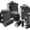
If you are looking for a way to quickly fixture a number of round parts, Vektek's collet vises are an excellent solution. Designed to be flexible and conserve space, they can be ganged to fixture 3, 6, 9, 12 or more parts in a small space. Screw machine parts can be fixtured easily for speedy secondary operations. It is made to accept all collets designed to fit 5-C closers, even specials. The single, end located port even makes plumbing a breeze. |
  |
5-C Hydraulic Collet Vise
Specifications
 |
|
|||||||||||||||||||||||||||||||||||||||
|
||||||||||||||||||||||||||||||||||||||||
* Capacities are given at 5,000 psi maximum operation pressure.
** Collets not included.
5-C Pneumatic Collet Vise
Specifications
|
|||||||||||||||||||||||||||
|
|||||||||||||||||||||||||||
* At 100 psi air pressure with a Ø 0.500 collet
NOTE: Do not exceed 150 psi maximum inlet pressure
Pull Down Clamps
Specifications
 |
 |
|||||||||||||||||||||||||||||||||||||||||||||||||||||||
For proper sealing, mating surface must be flat within 0.003 in.
|
||||||||||||||||||||||||||||||||||||||||||||||||||||||||
|
||||||||||||||||||||||||||||||||||||||||||||||||||||||||
* Cylinder capacities are listed at 5,000 psi maximum operating pressure. The output force is adjustable by varying the hydraulic system pressure. (Actual force may vary slightly due to friction loss, seal and wiper drag, and/or return springs.)
|
|
 |
|||||||||||||||||||||||||
|
||||||||||||||||||||||||||

*Clamping Forces shown are for units operating at 5000 psi, the maximum operating pressure. Back pressure not to exceed 10 psi for consistent unclamping stroke.
Edge Clamps
Specifications
 |
 |
|||||||||||||||||||||||||||||||||||||||||||||||||||||||
For proper sealing, mating surface must be flat within 0.003 in. with a maximum 63 µin Ra surface finish |
||||||||||||||||||||||||||||||||||||||||||||||||||||||||
|
||||||||||||||||||||||||||||||||||||||||||||||||||||||||
Manifold mating surface shoud be flat to .003, with a maximum RA63 surface finish.
* Cylinder capacities are listed at 5,000 psi maximum operating pressure. The output force is adjustable by varying hydraulic system pressure. (Actual force may vary slightly due to friction loss, seal and wiper drag, and/or return springs.)
ID Expansion Clamps
Features
|
 |
Centering Clamp, Small Bore – 3 Point Contact
Double Acting
|
 |
|
||||||||||||||||||||||||||||||||||||||||||||||||||||||||||||||
Centering Clamp, Small Bore, 2 Point Contact
Double Acting
|
 |
|
||||||||||||||||||||||||||||||||||||||||||||||||||||||||||||||
Special Use Clamps
|
 |
Centering Clamps
Small Bore and Large Bore Centering Clamps with 2 or 3 centering posts
|
Centering Clamps are essentially a bore clamp used for locating a part. They are capable of centering parts using a rough or finished bored hole. Internal clamping posts expands radially to the bore diameter of the workpiece to be clamped. If 1 clamp is used, most applications call for a 3 point clamp to center the bore, if a second bore clamp is to be used, a 2 point clamp provides centering and clocking for the secondary bore. Position repeatability ±.001”. We offer two styles of Centering Clamps, with either 2 or 3 clamping points, in Small and Large Bore sizes. The Small size centers bores .98” to 2.17”. The Large size clamps bores 2.13” to 5.12.” |
 A simple cavity design makes machining for manifold mounting simple. Hydraulic fluid is supplied through manifold channels drilled in the fixture body. Alternatively if surface mounted, hydraulic fluid may be supplied through a connection plate. Connection plates are available for either pipe connections or bolt down O-ring manifold mounting. A simple cavity design makes machining for manifold mounting simple. Hydraulic fluid is supplied through manifold channels drilled in the fixture body. Alternatively if surface mounted, hydraulic fluid may be supplied through a connection plate. Connection plates are available for either pipe connections or bolt down O-ring manifold mounting. Note: Centering Clamps are not suitable for use on lathes or without additional clamps for holding against rotational forces. Be sure that your bore will not be damaged by contact from the posts which contact the part. |
 |
 |
Collet Vises
|
If you are looking for a way to quickly fixture a number of round parts, Vektek's collet vises are an excellent solution. Designed to be flexible and conserve space, they can be ganged to fixture 3, 6, 9, 12 or more parts in a small space. Screw machine parts can be fixtured easily for speedy secondary operations. It is made to accept all collets designed to fit 5-C closers, even specials. The single, end located port even makes plumbing a breeze. |
|
5-C Hydraulic Collet Vise
Specifications
|
|
|||||||||||||||||||||||||||||||||||||||
|
||||||||||||||||||||||||||||||||||||||||
* Capacities are given at 5,000 psi maximum operation pressure.
** Collets not included.
5-C Pneumatic Collet Vise
Specifications
|
|||||||||||||||||||||||||||
|
|||||||||||||||||||||||||||
* At 100 psi air pressure with a Ø 0.500 collet
NOTE: Do not exceed 150 psi maximum inlet pressure
Pull Down Clamps
Specifications
|
|
|||||||||||||||||||||||||||||||||||||||||||||||||||||||
For proper sealing, mating surface must be flat within 0.003 in.
|
||||||||||||||||||||||||||||||||||||||||||||||||||||||||
|
||||||||||||||||||||||||||||||||||||||||||||||||||||||||
* Cylinder capacities are listed at 5,000 psi maximum operating pressure. The output force is adjustable by varying the hydraulic system pressure. (Actual force may vary slightly due to friction loss, seal and wiper drag, and/or return springs.)
|
|
|
|||||||||||||||||||||||||
|
||||||||||||||||||||||||||
*Clamping Forces shown are for units operating at 5000 psi, the maximum operating pressure. Back pressure not to exceed 10 psi for consistent unclamping stroke.
Edge Clamps
Specifications
|
|
|||||||||||||||||||||||||||||||||||||||||||||||||||||||
For proper sealing, mating surface must be flat within 0.003 in. with a maximum 63 µin Ra surface finish |
||||||||||||||||||||||||||||||||||||||||||||||||||||||||
|
||||||||||||||||||||||||||||||||||||||||||||||||||||||||
Manifold mating surface shoud be flat to .003, with a maximum RA63 surface finish.
* Cylinder capacities are listed at 5,000 psi maximum operating pressure. The output force is adjustable by varying hydraulic system pressure. (Actual force may vary slightly due to friction loss, seal and wiper drag, and/or return springs.)
ID Expansion Clamps
Features
|
|
Centering Clamp, Small Bore – 3 Point Contact
Double Acting
|
|
|
||||||||||||||||||||||||||||||||||||||||||||||||||||||||||||||
Centering Clamp, Small Bore, 2 Point Contact
Double Acting
|
|
|
||||||||||||||||||||||||||||||||||||||||||||||||||||||||||||||
Special Use Clamps
|
|
Centering Clamps
Small Bore and Large Bore Centering Clamps with 2 or 3 centering posts
|
Centering Clamps are essentially a bore clamp used for locating a part. They are capable of centering parts using a rough or finished bored hole. Internal clamping posts expands radially to the bore diameter of the workpiece to be clamped. If 1 clamp is used, most applications call for a 3 point clamp to center the bore, if a second bore clamp is to be used, a 2 point clamp provides centering and clocking for the secondary bore. Position repeatability ±.001”. We offer two styles of Centering Clamps, with either 2 or 3 clamping points, in Small and Large Bore sizes. The Small size centers bores .98” to 2.17”. The Large size clamps bores 2.13” to 5.12.” |
A simple cavity design makes machining for manifold mounting simple. Hydraulic fluid is supplied through manifold channels drilled in the fixture body. Alternatively if surface mounted, hydraulic fluid may be supplied through a connection plate. Connection plates are available for either pipe connections or bolt down O-ring manifold mounting. Note: Centering Clamps are not suitable for use on lathes or without additional clamps for holding against rotational forces. Be sure that your bore will not be damaged by contact from the posts which contact the part. |
|
|