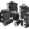
Tufflink 360 - Rotary Lug Link Clamps
- Single acting available in five sizes from 600 lb to 3600 lb capacities at 5000 psi.
- Double acting available in six sizes from 600 lb to 5000 lb capacities at 5000 psi.
- Highly effective internal spring design provides fastest Single Aacting return times.
- Patented rotary lug feature delivers 360° of lever and/or body positioning.
- Top flange manifold mounted or plumbed.
- Maximum clamping force - Minimal footprint.
- Independent body/lever adjustment simplifies manifold mount drill passage design or plumbing position and installation.
- Optional in-port flow control is a meter-in device with reverse free flow check valve.
- Levers sold separately.

|

|
Standard Link Clamps
- Provides reach-over clamping for hard-to-hit points in a very rigid beam design
- Available in capacities from 450 to 6,800 lb. at 5,000 psi system pressure
- Double-acting models
- Standard fluorocarbon seals
- Ideal for vertical "drop-in" loading
|

|
Tufflink 360 - Rotary Lug Link Clamps
- Single acting available in five sizes from 600 lb to 3600 lb capacities at 5000 psi.
- Double acting available in six sizes from 600 lb to 5000 lb capacities at 5000 psi.
- Highly effective internal spring design provides fastest Single Aacting return times.
- Patented rotary lug feature delivers 360° of lever and/or body positioning.
- Top flange manifold mounted or plumbed.
- Maximum clamping force - Minimal footprint.
- Independent body/lever adjustment simplifies manifold mount drill passage design or plumbing position and installation.
- Optional in-port flow control is a meter-in device with reverse free flow check valve.
- Levers sold separately.
|
 |
Specifications
 |

For proper sealing, mating surface
must be flat within 0.003 in.
with a maximum 63 µin Ra surface finish.
|
| Model No. | Cylinder
Capacity (lb.) ** | Vertical
Clamping
Stroke **** | Effective
Piston Area (sq. in.) | Oil Capacity
(cu.in.) **** | Max.
Flow Rate
(cu. in./min.) *** |
Port X Depth
for Optional
In-Port
Valves****
|
|---|
| Extend | Retract |
|---|
| 16-3112-00 |
600 |
0.08 |
0.175 |
0.114 |
N/A |
14 |
SAE 4 X .58 |
| 16-3115-00 |
1000 |
0.10 |
0.274 |
0.213 |
N/A |
26 |
SAE 4 X .58
|
| 16-3118-00 |
1400 |
0.12 |
0.394 |
0.379 |
N/A |
45 |
SAE 4 X .58
|
| 16-3122-00 |
2400 |
0.14 |
0.589 |
0.684 |
N/A |
82 |
SAE 4 X .58
|
| 16-3128-00 |
3600 |
0.17 |
0.934 |
1.318 |
N/A |
158 |
SAE 4 X .75
|
|
Specifications
 |
For proper sealing, mating surface
must be flat within 0.003 in.
with a maximum 63 µin Ra surface finish.
|
| Model No. | Cylinder
Capacity (lb.) ** | Vertical
Clamping
Stroke **** | Effective
Piston Area (sq. in.) | Oil Capacity
(cu.in.) **** | Max.
Flow Rate
(cu. in./min.) *** |
Port X Depth
for Optional
In-Port
Valves****
|
|---|
| Extend | Retract |
|---|
| 16-3212-00 |
600 |
0.08 |
0.175 |
0.114 |
0.035 |
14 |
SAE 4 X .58
|
| 16-3215-00 |
1000 |
0.10 |
0.274 |
0.213 |
0.077 |
26 |
SAE 4 X .58
|
| 16-3218-00 |
1400 |
0.12 |
0.394 |
0.379 |
0.116 |
45 |
SAE 4 X .58
|
| 16-3222-00 |
2400 |
0.14 |
0.616 |
0.684 |
0.258 |
86 |
SAE 4 X .58
|
|
16-3228-00
|
3600 |
0.17 |
0.954 |
1.318 |
0.504 |
158 |
SAE 4 X .75
|
| 16-3232-00 |
5000 |
0.20 |
1.247 |
2.144 |
0.729
|
257 |
SAE 4 X .75
|
All dimensions in inches. |
NEW! SCREW-IN TWIN LEVER LINK CLAMP
Double Acting
- Available in 3 sizes, 1100lb, 1700lb, and 2600lb total clamping force at 5000 PSI.
- Significantly increased vertical clamping stroke over standard link clamp.
- Clamp through a hole onto the surface of your work piece.
- Clamp on two parts with one link clamp.
- Load equalizing mechanism allows uniform clamping when work piece surfaces are within 0.060 inches.
- Cartridge mount body is manifold mount only.
- Cartridge mount body minimizes clamp footprint with easy to machine cavity.
- Levers must clamp on a flat surface.
- Levers sold separately.
|
 |
Model
No. | Total
Clamping
Force
(lb)* | Vertical
Clamping
Stroke
(in)** | Effective
Piston
Area
(sq. in.)
Extend | Oil
Capacity
(cu. in.) | Maximum
Flow Rate***
(cu. in./min.) |
|---|
| Extend | Retract |
|---|
| 16-4215-20 |
1,100 |
0.18 |
0.274 |
0.141 |
0.051 |
17 |
| 16-4218-20 |
1,700 |
0.24 |
0.394 |
0.259 |
0.080 |
31 |
| 16-4222-20 |
2,600 |
0.29 |
0.616 |
0.511 |
0.186 |
61 |
Force equally divided between each side.
* Clamp capacities are listed at 5000 PSI maximum operating pressure with a standard length link clamp lever installed. Total clamping force is divided equally between each side. Minimum operating pressure is 500 PSI for double acting. The clamping force is adjustable by varying the hydraulic system pressure. Use of an extended length lever will result in a reduction of clamp force. (Actual force will vary slightly due to mechanical inefficiencies, and friction.) Concentric design allows reaching up through a bore to clamp a single part.
** Equal to ±10° with standard lever.
*** To ensure maximum service life and trouble-free operation, restrict fluid flow to the above flow ratings when clamping. If you are unable to measure flow rates, these devices should be positioned in no less than 1/2 second. These recommendations apply when using the standard lever. When using the optional extended lever or your custom lever, please restrict the flow rates to position the lever in no less than 1 second.
|
NEW! Top Flange Twin Link Clamp
Double Acting Rotary Lug
- Made possible by Vektek’s patented equalizing system!
- Patented rotary lug feature delivers 360 degrees of lever/body positioning. This simplifies internal porting and fixture design flexibility.
- Available in 3 sizes, 1100lb, 1700lb, and 2600lb total clamping force at 5000 PSI.
- Significantly increased vertical clamping stroke over standard link clamp allows access to clamp through a hole onto the surface of work piece.
- Clamp on two parts with one link clamp.
- For clamping when work piece surfaces are within 0.060 inches.
- Top flange body can be manifold mounted or plumbed.
- Optional In The Port Flow Control is a meter-in device with reverse free flow check valve.
- Optional In The Port Sequence Valve is a sequencing device with reverse free flow check valve.
|
 |
Model
No. | Total
Clamping
Force
(lb)* | Vertical
Clamping
Stroke
(in)** | Effective
Piston
Area
(sq. in.)
Extend | Oil
Capacity
(cu. in.) | Maximum
Flow Rate***
(cu. in./min.) |
|---|
| Extend | Retract |
|---|
| 16-3215-20 |
1,100 |
0.18 |
0.274 |
0.141 |
0.051 |
17 |
| 16-3218-20 |
1,700 |
0.24 |
0.394 |
0.259 |
0.080 |
31 |
| 16-3222-20 |
2,600 |
0.29 |
0.616 |
0.511 |
0.186 |
61 |
Port Depth for Optional In-Port Valves: SAE 4 X .58 In-port valves require the use of manifold mount ports. Force equally divided between each side.
* Clamp capacities are listed at 5000 PSI maximum operating pressure with a standard length link clamp lever installed. Total clamping force is divided equally between each side. Minimum operating pressure is 500 PSI for double acting. The clamping force is adjustable by varying the hydraulic system pressure. Use of an extended length lever will result in a reduction of clamp force. (Actual force will vary slightly due to mechanical inefficiencies, and friction.)
** Equal to ±10° with standard lever.
*** To ensure maximum service life and trouble-free operation, restrict fluid flow to the above flow ratings when clamping. If you are unable to measure flow rates, these devices should be positioned in no less than 1/2 second. These recommendations apply when using the standard lever. When using the optional extended lever or your custom lever, please restrict the flow rates to position the lever in no less than 1 second.
|
NEW! Screw-In Single Lever Link Clamp
Double Acting Single Lever
- Patented rotary lug feature delivers 360 degrees of lever/body positioning.
- Available in 4 sizes, 600lb, 1000lb, 1400lb, and 2400lb total clamping force at 5000 PSI.
- Cartridge mount body is manifold mount only.
- Cartridge mount body minimizes clamp footprint with easy to machine cavity.
- Maximum clamping force - minimal footprint.
- Levers sold separately.
|
 |
 |
Model
No. | Clamping
Capacity
(lb)* | Vertical
Clamping
Stroke
(in)** | Effective
Piston
Area
(sq. in.)
Extend | Oil
Capacity
(cu. in.) | Maximum
Flow Rate***
(cu. in./min.) |
|---|
| Extend | Retract |
|---|
| 16-4212-00 |
600 |
0.08 |
0.175 |
0.114 |
0.035 |
14 |
| 16-4215-00 |
1,000 |
0.10 |
0.274 |
0.213 |
0.077 |
26 |
| 16-4218-00 |
1,400 |
0.12 |
0.394 |
0.379 |
0.116 |
45 |
| 16-4222-00 |
2,400 |
0.14 |
0.616 |
0.715 |
0.258 |
86 |
* Clamp capacities are listed at 5000 PSI maximum operating pressure with a standard length link clamp lever installed. Minimum operating pressure is 500 PSI for double acting. The clamping force is adjustable by varying the hydraulic system pressure. Use of an extended length lever will result in a reduction of clamp force. (Actual force will vary slightly due to mechanical inefficiencies, and friction.)
** Equal to ±3° with standard lever.
*** To ensure maximum service life and trouble-free operation, restrict fluid flow to the above flow ratings when clamping. If you are unable to measure flow rates, these devices should be positioned in no less than 1/2 second. These recommendations apply when using the standard lever. When using the optional extended lever or your custom lever, please restrict the flow rates to position the lever in no less than 1 second.
|
 |
 |
 |
| Model No. | Link Clamp
Model No. | A | B | C | D | E | F | G
Max | G
Min | H | J |
|---|
| 91-6112-01 |
16-3x12-00 |
1.38 |
1.613 |
0.551 |
0.472 |
0.197 |
0.197 |
0.1984 |
0.1972 |
0.591 |
0.118 |
| 91-6115-01 |
16-XX15-00 |
1.63 |
1.914 |
0.709 |
0.551 |
0.236 |
0.236 |
0.2378 |
0.2366 |
0.709 |
0.197 |
| 91-6118-01 |
16-XX18-00 |
2.01 |
2.365 |
0.787 |
0.709 |
0.315 |
0.315 |
0.3169 |
0.3155 |
0.866 |
0.118 |
| 91-6122-01 |
16-XX22-00 |
2.32 |
2.756 |
0.984 |
0.866 |
0.394 |
0.394 |
0.3956 |
0.3942 |
1.043 |
0.157 |
| 91-6128-01 |
16-3X28-00 |
2.83 |
3.348 |
1.181 |
1.024 |
0.472 |
0.472 |
0.4748 |
0.4731 |
1.260 |
0.197 |
| 91-6132-01 |
16-3X32-00 |
3.41 |
4.039 |
1.417 |
1.260 |
0.551 |
0.551 |
0.5535 |
0.5518 |
1.575 |
0.236 |
| 91-6112-02 |
16-3X12-00 |
1.38 |
2.403 |
0.551 |
0.472 |
0.197 |
0.197 |
0.1984 |
0.1972 |
0.591 |
0.118 |
| 91-6115-02 |
16-XX15-00 |
1.63 |
2.834 |
0.709 |
0.551 |
0.236 |
0.236 |
0.2378 |
0.2366 |
0.709 |
0.197 |
| 91-6118-02 |
16-XX18-00 |
2.01 |
3.505 |
0.787 |
0.709 |
0.315 |
0.315 |
0.3169 |
0.3155 |
0.866 |
0.118 |
| 91-6122-02 |
16-XX22-00 |
2.32 |
4.036 |
0.984 |
0.866 |
0.394 |
0.394 |
0.3956 |
0.3942 |
1.043 |
0.157 |
| 91-6128-02 |
16-3X28-00 |
2.83 |
4.918 |
1.181 |
1.024 |
0.472 |
0.472 |
0.4748 |
0.4731 |
1.260 |
0.197 |
| 91-6132-02 |
16-3X32-00 |
3.41 |
5.869 |
1.417 |
1.260 |
0.551 |
0.551 |
0.5535 |
0.5518 |
1.575 |
0.236 |
| Model No. | Link Clamp
Model No. | K
Max | K
Min | L
Min | M | N | Q | R | S | T |
|---|
| 91-6112-01 |
16-3X12-00 |
0.2369 |
0.2362 |
0.433 |
0.209 |
0.54 |
0.54 |
1/4-20 UNC |
0.156 |
0.437 |
| 91-6115-01 |
16-XX15-00 |
0.2765 |
0.2756 |
0.520 |
0.248 |
0.64 |
0.64 |
5/16-18 UNC |
0.187 |
0.500 |
| 91-6118-01 |
16-XX18-00 |
0.3552 |
0.3543 |
0.693 |
0.327 |
0.86 |
0.86 |
3/8-16 UNC |
0.219 |
0.562 |
| 91-6122-01 |
16-XX22-00 |
0.4341 |
0.4331 |
0.866 |
0.406 |
0.107 |
1.07 |
1/2-13 UNC |
0.312 |
0.750 |
| 91-6128-01 |
16-3X28-00 |
0.5129 |
0.5118 |
1.039 |
0.484 |
0.128 |
1.28 |
5/8-11 UNC |
0.375 |
0.937 |
| 91-6132-01 |
16-3X32-00 |
0.6310 |
0.6299 |
1.213 |
0.563 |
1.49 |
1.49 |
3/4-10 UNC |
0.422 |
1.125 |
| 91-6112-02 |
16-3X12-00 |
0.2369 |
0.2362 |
0.433 |
0.209 |
0.54 |
No Contact Bolt |
| 91-6115-02 |
16-XX15-00 |
0.2765 |
0.2756 |
0.520 |
0.248 |
0.64 |
No Contact Bolt |
| 91-6118-02 |
16-XX18-00 |
0.3552 |
0.3543 |
0.693 |
0.327 |
0.86 |
No Contact Bolt |
| 91-6122-02 |
16-XX22-00 |
0.4341 |
0.4331 |
0.866 |
0.406 |
1.07 |
No Contact Bolt |
| 91-6128-02 |
16-XX28-00 |
0.5129 |
0.5118 |
1.039 |
0.484 |
1.28 |
No Contact Bolt |
| 91-6132-02 |
16-XX32-00 |
0.6310 |
0.6299 |
1.213 |
0.563 |
1.49 |
No Contact Bolt |
|
NEW! TWIN LEVER LINK CLAMP LEVERS
Dimensions
Model
No. | Link Clamp
Model No. | A | B | C | D | E | F | G | H | J | K |
|---|
| MAX | MIN |
|---|
| 91-6115-20 |
16-X215-20 |
1.18 |
1.51 |
0.551 |
0.472 |
0.167 |
0.197 |
0.197 |
0.1984 |
0.1972 |
0.551 |
0.118 |
| 91-6118-20 |
16-X218-20 |
1.48 |
1.87 |
0.709 |
0.551 |
0.197 |
0.276 |
0.197 |
0.2378 |
0.2366 |
0.719 |
0.157 |
| 91-6122-20 |
16-X222-20 |
1.76 |
2.24 |
0.787 |
0.709 |
0.256 |
0.354 |
0.236 |
0.3169 |
0.3155 |
0.856 |
0.079 |
|
Model
No. | Link Clamp
Model No. | L | M | N | P | Q | R | S | T | U |
|---|
| MAX | MIN |
|---|
| 91-6115-20 |
16-X215-20 |
0.2370 |
0.2362 |
25 |
0.280 |
0.370 |
0.197 |
0.451 |
27 |
0.197 |
0.167 |
| 91-6118-20 |
16-X218-20 |
0.2764 |
0.2756 |
30 |
0.319 |
0.453 |
0.217 |
0.524 |
29 |
0.256 |
0.197 |
| 91-6122-20 |
16-X222-20 |
0.3552 |
0.3544 |
25 |
0.398 |
0.630 |
0.355 |
0.591 |
25 |
0.394 |
0.256 |
|
High Pressure Link Clamps
Specifications
 |
 |
| Model No. | Cylinder Capacity (lb.) ** | Vertical Clamping Stroke **** | Body
Thread | Standard Lever Length | Effective Piston Area (sq. in.) | Oil Capacity (cu.in.) **** | Max. Flow Rate (cu. in./min.) *** |
Port X Depth for Optional
In-Port Valves*****
|
|---|
| Extend | Retract |
|---|
| 16-6104-00 |
350 |
0.09 |
1-1/16 - 16 UN |
0.88 |
0.076 |
0.103 |
N/A |
12 |
SAE 2 X .48 |
| 16-6106-00 |
700 |
0.12 |
1-1/2 - 16 UN |
1.13 |
0.150 |
0.287 |
N/A |
34 |
SAE 4 X .58 |
| 16-6109-00 |
1300 |
0.14 |
1-7/8 - 16 UN |
1.38 |
0.307 |
0.821 |
N/A |
98 |
SAE 4 X .58 |
| 16-6114-00 |
3000 |
0.18 |
2-1/2 - 16 UN |
1.75 |
0.785 |
2.148 |
N/A |
258 |
SAE 4 X .58 |
| 16-6116-00 |
5000 |
0.22 |
3-1/8 - 16 UN |
2.13 |
1.227 |
3.755 |
N/A |
450 |
SAE 4 X .75 |
| 16-6204-00 |
450 |
0.09 |
1-1/16 - 16 UN |
0.88 |
0.110 |
0.103 |
0.032 |
12 |
SAE 2 X .48 |
| 16-6206-00 |
1100 |
0.12 |
1-1/2 - 16 UN |
1.13 |
0.248 |
0.287 |
0.113 |
34 |
SAE 4 X .58 |
| 16-6209-00 |
2600 |
0.14 |
1-7/8 - 16 UN |
1.38 |
0.601 |
0.821 |
0.405 |
98 |
SAE 4 X .58 |
| 16-6214-00 |
5000 |
0.18 |
2-1/2 - 16 UN |
1.75 |
1.227 |
2.148 |
0.773 |
258 |
SAE 4 X .58 |
| 16-6216-00 |
6800 |
0.22 |
3-1/8 - 16 UN |
2.13 |
1.767 |
3.755 |
1.147 |
450 |
SAE 4 X .75 |
|
** Clamp capacities are listed at 5000 psi maximum operating pressure with a standard length link clamp lever installed. Minimum operating pressure is 750 psi for single acting and 500 psi for double acting devices. The clamping force is adjustable by varying the hydraulic system pressure. To determine the approximate output force for your application, divide the clamp capacity shown above by 5,000 and multiply the resultant number by your system operating pressure to obtain the approximate clamping force for your application. (Actual force will vary slightly due to mechanical inefficiencies and friction.)
*** To insure maximum service life and trouble-free operation , restrict fluid flow to the above flow ratings when clamping. If you are unable to measure flow rates, the devices should be positioned in no less than ½ second. These recommendations apply when using the standard lever. When using the optional long lever or your custom lever, please restrict the flow rates to position the lever in no less than 1 second.
**** Equal ± 3° with standard lever
***** In-Port Valves require the use of manifold mount ports.
Low Pressure Link Clamps
Specifications
 |
 |
| Model No. | Lever Position | Cylinder Capacity (lb.)* | Vertical Clamping Stroke **** | Standard Lever Length | Effective Piston Area
(sq. in.) | Oil Capacity (cu.in.) | Max. Flow Rate
(cu. in./min.) *** |
Port X Depth for Optional
In-Port
Valves*****
|
|---|
| Extend | Retract |
|---|
16-6211-00
16-6211-01
16-6211-02 |
Forward
Right
Left |
550 |
0.09 |
1.875 |
0.785 |
0.712 |
0.433 |
85.43 |
SAE 2 X .48 |
16-6215-00
16-6215-01
16-6215-02 |
Forward
Right
Left |
1100 |
0.125 |
2.625 |
1.767 |
1.988 |
1.491 |
238.60 |
SAE 4 X .58 |
16-6221-00
16-6221-01
16-6221-02 |
Forward
Right
Left |
2200 |
0.125 |
3.094 |
3.546 |
4.514 |
4.111 |
541.89 |
SAE 4 X .58 |
|
Link Clamp Levers
High Pressure Link Clamp Lever Dimensions
 |
 |
| Model No. | Link Clamp
Model No.* | A | B | C | D | E | F | G |
|---|
| 91-6004-01 |
16-6X04-00 |
1.75 |
2.00 |
0.63 |
0.500 |
0.188 |
0.19 |
0.1885 |
| 91-6006-01 |
16-6X06-00 |
2.25 |
2.50 |
0.88 |
0.625 |
0.250 |
0.25 |
0.2515 |
| 91-6009-01 |
16-6X09-00 |
2.75 |
3.13 |
1.25 |
1.000 |
0.375 |
0.38 |
0.3765 |
| 91-6014-01 |
16-6X14-00 |
3.50 |
4.00 |
1.75 |
1.250 |
0.500 |
0.50 |
0.5015 |
| 91-6016-01 |
16-6X16-00 |
4.25 |
4.88 |
2.00 |
1.500 |
0.625 |
0.63 |
0.6265 |
| 91-6004-02 |
16-6X04-00 |
N/A |
2.88 |
0.63 |
0.500 |
0.188 |
0.19 |
0.1885 |
| 91-6006-02 |
16-6X06-00 |
N/A |
2.88 |
0.63 |
0.500 |
0.188 |
0.19 |
0.1885 |
| 91-6009-02 |
16-6X09-00 |
N/A |
4.50 |
1.25 |
1.000 |
0.375 |
0.38 |
0.3765 |
| 91-6014-02 |
16-6X14-00 |
N/A |
5.75 |
1.75 |
1.250 |
0.500 |
0.50 |
0.5015 |
| 91-6016-02 |
16-6X16-00 |
N/A |
7.00 |
2.00 |
1.500 |
0.625 |
0.63 |
0.6265 |
| Model No. | H | J | K | L | M | N | Q | R | S | T |
|---|
| 91-6004-01 |
0.88 |
0.13 |
0.2505 |
0.44 |
0.260 |
0.44 |
1.25 |
1/4-20 UNC |
0.19 |
0.433 |
| 91-6006-01 |
1.13 |
0.13 |
0.3755 |
0.56 |
0.322 |
0.56 |
1.75 |
5/16-18 UNC |
0.24 |
0.495 |
| 91-6009-01 |
1.38 |
0.19 |
0.5005 |
0.81 |
0.510 |
0.81 |
2.25 |
3/8-16 UNC |
0.28 |
0.577 |
| 91-6014-01 |
1.75 |
0.25 |
0.6255 |
1.19 |
0.635 |
1.19 |
3.00 |
1/2-13 UNC |
0.38 |
0.743 |
| 91-6016-01 |
2.13 |
0.25 |
0.7505 |
1.50 |
0.760 |
1.50 |
3.50 |
5/8-11 UNC |
0.47 |
0.930 |
| 91-6004-02 |
0.88 |
0.13 |
0.2505 |
0.44 |
0.260 |
0.44 |
N/A |
N/A |
N/A |
N/A |
| 91-6006-02 |
1.13 |
0.13 |
0.3775 |
0.56 |
0.322 |
0.56 |
N/A |
N/A |
N/A |
N/A |
| 91-6009-02 |
1.38 |
0.19 |
0.5005 |
0.81 |
0.550 |
0.81 |
N/A |
N/A |
N/A |
N/A |
| 91-6014-02 |
1.75 |
0.25 |
0.6255 |
1.19 |
0.635 |
1.19 |
N/A |
N/A |
N/A |
N/A |
| 91-6016-02 |
2.13 |
0.25 |
0.7505 |
1.50 |
0.760 |
1.50 |
N/A |
N/A |
N/A |
N/A |
|
All dimensions are in inches.
*Link Clamps to be ordered separately.
Tufflink 360 - Rotary Lug Link Clamps
- Single acting available in five sizes from 600 lb to 3600 lb capacities at 5000 psi.
- Double acting available in six sizes from 600 lb to 5000 lb capacities at 5000 psi.
- Highly effective internal spring design provides fastest Single Aacting return times.
- Patented rotary lug feature delivers 360° of lever and/or body positioning.
- Top flange manifold mounted or plumbed.
- Maximum clamping force - Minimal footprint.
- Independent body/lever adjustment simplifies manifold mount drill passage design or plumbing position and installation.
- Optional in-port flow control is a meter-in device with reverse free flow check valve.
- Levers sold separately.
|
|
Standard Link Clamps
- Provides reach-over clamping for hard-to-hit points in a very rigid beam design
- Available in capacities from 450 to 6,800 lb. at 5,000 psi system pressure
- Double-acting models
- Standard fluorocarbon seals
- Ideal for vertical "drop-in" loading
|
|
Tufflink 360 - Rotary Lug Link Clamps
- Single acting available in five sizes from 600 lb to 3600 lb capacities at 5000 psi.
- Double acting available in six sizes from 600 lb to 5000 lb capacities at 5000 psi.
- Highly effective internal spring design provides fastest Single Aacting return times.
- Patented rotary lug feature delivers 360° of lever and/or body positioning.
- Top flange manifold mounted or plumbed.
- Maximum clamping force - Minimal footprint.
- Independent body/lever adjustment simplifies manifold mount drill passage design or plumbing position and installation.
- Optional in-port flow control is a meter-in device with reverse free flow check valve.
- Levers sold separately.
|
|
Specifications
|
For proper sealing, mating surface
must be flat within 0.003 in.
with a maximum 63 µin Ra surface finish.
|
| Model No. | Cylinder
Capacity (lb.) ** | Vertical
Clamping
Stroke **** | Effective
Piston Area (sq. in.) | Oil Capacity
(cu.in.) **** | Max.
Flow Rate
(cu. in./min.) *** |
Port X Depth
for Optional
In-Port
Valves****
|
|---|
| Extend | Retract |
|---|
| 16-3112-00 |
600 |
0.08 |
0.175 |
0.114 |
N/A |
14 |
SAE 4 X .58 |
| 16-3115-00 |
1000 |
0.10 |
0.274 |
0.213 |
N/A |
26 |
SAE 4 X .58
|
| 16-3118-00 |
1400 |
0.12 |
0.394 |
0.379 |
N/A |
45 |
SAE 4 X .58
|
| 16-3122-00 |
2400 |
0.14 |
0.589 |
0.684 |
N/A |
82 |
SAE 4 X .58
|
| 16-3128-00 |
3600 |
0.17 |
0.934 |
1.318 |
N/A |
158 |
SAE 4 X .75
|
|
Specifications
|
For proper sealing, mating surface
must be flat within 0.003 in.
with a maximum 63 µin Ra surface finish.
|
| Model No. | Cylinder
Capacity (lb.) ** | Vertical
Clamping
Stroke **** | Effective
Piston Area (sq. in.) | Oil Capacity
(cu.in.) **** | Max.
Flow Rate
(cu. in./min.) *** |
Port X Depth
for Optional
In-Port
Valves****
|
|---|
| Extend | Retract |
|---|
| 16-3212-00 |
600 |
0.08 |
0.175 |
0.114 |
0.035 |
14 |
SAE 4 X .58
|
| 16-3215-00 |
1000 |
0.10 |
0.274 |
0.213 |
0.077 |
26 |
SAE 4 X .58
|
| 16-3218-00 |
1400 |
0.12 |
0.394 |
0.379 |
0.116 |
45 |
SAE 4 X .58
|
| 16-3222-00 |
2400 |
0.14 |
0.616 |
0.684 |
0.258 |
86 |
SAE 4 X .58
|
|
16-3228-00
|
3600 |
0.17 |
0.954 |
1.318 |
0.504 |
158 |
SAE 4 X .75
|
| 16-3232-00 |
5000 |
0.20 |
1.247 |
2.144 |
0.729
|
257 |
SAE 4 X .75
|
All dimensions in inches. |
NEW! SCREW-IN TWIN LEVER LINK CLAMP
Double Acting
- Available in 3 sizes, 1100lb, 1700lb, and 2600lb total clamping force at 5000 PSI.
- Significantly increased vertical clamping stroke over standard link clamp.
- Clamp through a hole onto the surface of your work piece.
- Clamp on two parts with one link clamp.
- Load equalizing mechanism allows uniform clamping when work piece surfaces are within 0.060 inches.
- Cartridge mount body is manifold mount only.
- Cartridge mount body minimizes clamp footprint with easy to machine cavity.
- Levers must clamp on a flat surface.
- Levers sold separately.
|
|
Model
No. | Total
Clamping
Force
(lb)* | Vertical
Clamping
Stroke
(in)** | Effective
Piston
Area
(sq. in.)
Extend | Oil
Capacity
(cu. in.) | Maximum
Flow Rate***
(cu. in./min.) |
|---|
| Extend | Retract |
|---|
| 16-4215-20 |
1,100 |
0.18 |
0.274 |
0.141 |
0.051 |
17 |
| 16-4218-20 |
1,700 |
0.24 |
0.394 |
0.259 |
0.080 |
31 |
| 16-4222-20 |
2,600 |
0.29 |
0.616 |
0.511 |
0.186 |
61 |
Force equally divided between each side.
* Clamp capacities are listed at 5000 PSI maximum operating pressure with a standard length link clamp lever installed. Total clamping force is divided equally between each side. Minimum operating pressure is 500 PSI for double acting. The clamping force is adjustable by varying the hydraulic system pressure. Use of an extended length lever will result in a reduction of clamp force. (Actual force will vary slightly due to mechanical inefficiencies, and friction.) Concentric design allows reaching up through a bore to clamp a single part.
** Equal to ±10° with standard lever.
*** To ensure maximum service life and trouble-free operation, restrict fluid flow to the above flow ratings when clamping. If you are unable to measure flow rates, these devices should be positioned in no less than 1/2 second. These recommendations apply when using the standard lever. When using the optional extended lever or your custom lever, please restrict the flow rates to position the lever in no less than 1 second.
|
NEW! Top Flange Twin Link Clamp
Double Acting Rotary Lug
- Made possible by Vektek’s patented equalizing system!
- Patented rotary lug feature delivers 360 degrees of lever/body positioning. This simplifies internal porting and fixture design flexibility.
- Available in 3 sizes, 1100lb, 1700lb, and 2600lb total clamping force at 5000 PSI.
- Significantly increased vertical clamping stroke over standard link clamp allows access to clamp through a hole onto the surface of work piece.
- Clamp on two parts with one link clamp.
- For clamping when work piece surfaces are within 0.060 inches.
- Top flange body can be manifold mounted or plumbed.
- Optional In The Port Flow Control is a meter-in device with reverse free flow check valve.
- Optional In The Port Sequence Valve is a sequencing device with reverse free flow check valve.
|
|
Model
No. | Total
Clamping
Force
(lb)* | Vertical
Clamping
Stroke
(in)** | Effective
Piston
Area
(sq. in.)
Extend | Oil
Capacity
(cu. in.) | Maximum
Flow Rate***
(cu. in./min.) |
|---|
| Extend | Retract |
|---|
| 16-3215-20 |
1,100 |
0.18 |
0.274 |
0.141 |
0.051 |
17 |
| 16-3218-20 |
1,700 |
0.24 |
0.394 |
0.259 |
0.080 |
31 |
| 16-3222-20 |
2,600 |
0.29 |
0.616 |
0.511 |
0.186 |
61 |
Port Depth for Optional In-Port Valves: SAE 4 X .58 In-port valves require the use of manifold mount ports. Force equally divided between each side.
* Clamp capacities are listed at 5000 PSI maximum operating pressure with a standard length link clamp lever installed. Total clamping force is divided equally between each side. Minimum operating pressure is 500 PSI for double acting. The clamping force is adjustable by varying the hydraulic system pressure. Use of an extended length lever will result in a reduction of clamp force. (Actual force will vary slightly due to mechanical inefficiencies, and friction.)
** Equal to ±10° with standard lever.
*** To ensure maximum service life and trouble-free operation, restrict fluid flow to the above flow ratings when clamping. If you are unable to measure flow rates, these devices should be positioned in no less than 1/2 second. These recommendations apply when using the standard lever. When using the optional extended lever or your custom lever, please restrict the flow rates to position the lever in no less than 1 second.
|
NEW! Screw-In Single Lever Link Clamp
Double Acting Single Lever
- Patented rotary lug feature delivers 360 degrees of lever/body positioning.
- Available in 4 sizes, 600lb, 1000lb, 1400lb, and 2400lb total clamping force at 5000 PSI.
- Cartridge mount body is manifold mount only.
- Cartridge mount body minimizes clamp footprint with easy to machine cavity.
- Maximum clamping force - minimal footprint.
- Levers sold separately.
|
|
|
Model
No. | Clamping
Capacity
(lb)* | Vertical
Clamping
Stroke
(in)** | Effective
Piston
Area
(sq. in.)
Extend | Oil
Capacity
(cu. in.) | Maximum
Flow Rate***
(cu. in./min.) |
|---|
| Extend | Retract |
|---|
| 16-4212-00 |
600 |
0.08 |
0.175 |
0.114 |
0.035 |
14 |
| 16-4215-00 |
1,000 |
0.10 |
0.274 |
0.213 |
0.077 |
26 |
| 16-4218-00 |
1,400 |
0.12 |
0.394 |
0.379 |
0.116 |
45 |
| 16-4222-00 |
2,400 |
0.14 |
0.616 |
0.715 |
0.258 |
86 |
* Clamp capacities are listed at 5000 PSI maximum operating pressure with a standard length link clamp lever installed. Minimum operating pressure is 500 PSI for double acting. The clamping force is adjustable by varying the hydraulic system pressure. Use of an extended length lever will result in a reduction of clamp force. (Actual force will vary slightly due to mechanical inefficiencies, and friction.)
** Equal to ±3° with standard lever.
*** To ensure maximum service life and trouble-free operation, restrict fluid flow to the above flow ratings when clamping. If you are unable to measure flow rates, these devices should be positioned in no less than 1/2 second. These recommendations apply when using the standard lever. When using the optional extended lever or your custom lever, please restrict the flow rates to position the lever in no less than 1 second.
|
| |
|
|
| Model No. | Link Clamp
Model No. | A | B | C | D | E | F | G
Max | G
Min | H | J |
|---|
| 91-6112-01 |
16-3x12-00 |
1.38 |
1.613 |
0.551 |
0.472 |
0.197 |
0.197 |
0.1984 |
0.1972 |
0.591 |
0.118 |
| 91-6115-01 |
16-XX15-00 |
1.63 |
1.914 |
0.709 |
0.551 |
0.236 |
0.236 |
0.2378 |
0.2366 |
0.709 |
0.197 |
| 91-6118-01 |
16-XX18-00 |
2.01 |
2.365 |
0.787 |
0.709 |
0.315 |
0.315 |
0.3169 |
0.3155 |
0.866 |
0.118 |
| 91-6122-01 |
16-XX22-00 |
2.32 |
2.756 |
0.984 |
0.866 |
0.394 |
0.394 |
0.3956 |
0.3942 |
1.043 |
0.157 |
| 91-6128-01 |
16-3X28-00 |
2.83 |
3.348 |
1.181 |
1.024 |
0.472 |
0.472 |
0.4748 |
0.4731 |
1.260 |
0.197 |
| 91-6132-01 |
16-3X32-00 |
3.41 |
4.039 |
1.417 |
1.260 |
0.551 |
0.551 |
0.5535 |
0.5518 |
1.575 |
0.236 |
| 91-6112-02 |
16-3X12-00 |
1.38 |
2.403 |
0.551 |
0.472 |
0.197 |
0.197 |
0.1984 |
0.1972 |
0.591 |
0.118 |
| 91-6115-02 |
16-XX15-00 |
1.63 |
2.834 |
0.709 |
0.551 |
0.236 |
0.236 |
0.2378 |
0.2366 |
0.709 |
0.197 |
| 91-6118-02 |
16-XX18-00 |
2.01 |
3.505 |
0.787 |
0.709 |
0.315 |
0.315 |
0.3169 |
0.3155 |
0.866 |
0.118 |
| 91-6122-02 |
16-XX22-00 |
2.32 |
4.036 |
0.984 |
0.866 |
0.394 |
0.394 |
0.3956 |
0.3942 |
1.043 |
0.157 |
| 91-6128-02 |
16-3X28-00 |
2.83 |
4.918 |
1.181 |
1.024 |
0.472 |
0.472 |
0.4748 |
0.4731 |
1.260 |
0.197 |
| 91-6132-02 |
16-3X32-00 |
3.41 |
5.869 |
1.417 |
1.260 |
0.551 |
0.551 |
0.5535 |
0.5518 |
1.575 |
0.236 |
| Model No. | Link Clamp
Model No. | K
Max | K
Min | L
Min | M | N | Q | R | S | T |
|---|
| 91-6112-01 |
16-3X12-00 |
0.2369 |
0.2362 |
0.433 |
0.209 |
0.54 |
0.54 |
1/4-20 UNC |
0.156 |
0.437 |
| 91-6115-01 |
16-XX15-00 |
0.2765 |
0.2756 |
0.520 |
0.248 |
0.64 |
0.64 |
5/16-18 UNC |
0.187 |
0.500 |
| 91-6118-01 |
16-XX18-00 |
0.3552 |
0.3543 |
0.693 |
0.327 |
0.86 |
0.86 |
3/8-16 UNC |
0.219 |
0.562 |
| 91-6122-01 |
16-XX22-00 |
0.4341 |
0.4331 |
0.866 |
0.406 |
0.107 |
1.07 |
1/2-13 UNC |
0.312 |
0.750 |
| 91-6128-01 |
16-3X28-00 |
0.5129 |
0.5118 |
1.039 |
0.484 |
0.128 |
1.28 |
5/8-11 UNC |
0.375 |
0.937 |
| 91-6132-01 |
16-3X32-00 |
0.6310 |
0.6299 |
1.213 |
0.563 |
1.49 |
1.49 |
3/4-10 UNC |
0.422 |
1.125 |
| 91-6112-02 |
16-3X12-00 |
0.2369 |
0.2362 |
0.433 |
0.209 |
0.54 |
No Contact Bolt |
| 91-6115-02 |
16-XX15-00 |
0.2765 |
0.2756 |
0.520 |
0.248 |
0.64 |
No Contact Bolt |
| 91-6118-02 |
16-XX18-00 |
0.3552 |
0.3543 |
0.693 |
0.327 |
0.86 |
No Contact Bolt |
| 91-6122-02 |
16-XX22-00 |
0.4341 |
0.4331 |
0.866 |
0.406 |
1.07 |
No Contact Bolt |
| 91-6128-02 |
16-XX28-00 |
0.5129 |
0.5118 |
1.039 |
0.484 |
1.28 |
No Contact Bolt |
| 91-6132-02 |
16-XX32-00 |
0.6310 |
0.6299 |
1.213 |
0.563 |
1.49 |
No Contact Bolt |
|
NEW! TWIN LEVER LINK CLAMP LEVERS
Dimensions
Model
No. | Link Clamp
Model No. | A | B | C | D | E | F | G | H | J | K |
|---|
| MAX | MIN |
|---|
| 91-6115-20 |
16-X215-20 |
1.18 |
1.51 |
0.551 |
0.472 |
0.167 |
0.197 |
0.197 |
0.1984 |
0.1972 |
0.551 |
0.118 |
| 91-6118-20 |
16-X218-20 |
1.48 |
1.87 |
0.709 |
0.551 |
0.197 |
0.276 |
0.197 |
0.2378 |
0.2366 |
0.719 |
0.157 |
| 91-6122-20 |
16-X222-20 |
1.76 |
2.24 |
0.787 |
0.709 |
0.256 |
0.354 |
0.236 |
0.3169 |
0.3155 |
0.856 |
0.079 |
|
Model
No. | Link Clamp
Model No. | L | M | N | P | Q | R | S | T | U |
|---|
| MAX | MIN |
|---|
| 91-6115-20 |
16-X215-20 |
0.2370 |
0.2362 |
25 |
0.280 |
0.370 |
0.197 |
0.451 |
27 |
0.197 |
0.167 |
| 91-6118-20 |
16-X218-20 |
0.2764 |
0.2756 |
30 |
0.319 |
0.453 |
0.217 |
0.524 |
29 |
0.256 |
0.197 |
| 91-6122-20 |
16-X222-20 |
0.3552 |
0.3544 |
25 |
0.398 |
0.630 |
0.355 |
0.591 |
25 |
0.394 |
0.256 |
|
High Pressure Link Clamps
Specifications
|
|
| Model No. | Cylinder Capacity (lb.) ** | Vertical Clamping Stroke **** | Body
Thread | Standard Lever Length | Effective Piston Area (sq. in.) | Oil Capacity (cu.in.) **** | Max. Flow Rate (cu. in./min.) *** |
Port X Depth for Optional
In-Port Valves*****
|
|---|
| Extend | Retract |
|---|
| 16-6104-00 |
350 |
0.09 |
1-1/16 - 16 UN |
0.88 |
0.076 |
0.103 |
N/A |
12 |
SAE 2 X .48 |
| 16-6106-00 |
700 |
0.12 |
1-1/2 - 16 UN |
1.13 |
0.150 |
0.287 |
N/A |
34 |
SAE 4 X .58 |
| 16-6109-00 |
1300 |
0.14 |
1-7/8 - 16 UN |
1.38 |
0.307 |
0.821 |
N/A |
98 |
SAE 4 X .58 |
| 16-6114-00 |
3000 |
0.18 |
2-1/2 - 16 UN |
1.75 |
0.785 |
2.148 |
N/A |
258 |
SAE 4 X .58 |
| 16-6116-00 |
5000 |
0.22 |
3-1/8 - 16 UN |
2.13 |
1.227 |
3.755 |
N/A |
450 |
SAE 4 X .75 |
| 16-6204-00 |
450 |
0.09 |
1-1/16 - 16 UN |
0.88 |
0.110 |
0.103 |
0.032 |
12 |
SAE 2 X .48 |
| 16-6206-00 |
1100 |
0.12 |
1-1/2 - 16 UN |
1.13 |
0.248 |
0.287 |
0.113 |
34 |
SAE 4 X .58 |
| 16-6209-00 |
2600 |
0.14 |
1-7/8 - 16 UN |
1.38 |
0.601 |
0.821 |
0.405 |
98 |
SAE 4 X .58 |
| 16-6214-00 |
5000 |
0.18 |
2-1/2 - 16 UN |
1.75 |
1.227 |
2.148 |
0.773 |
258 |
SAE 4 X .58 |
| 16-6216-00 |
6800 |
0.22 |
3-1/8 - 16 UN |
2.13 |
1.767 |
3.755 |
1.147 |
450 |
SAE 4 X .75 |
|
** Clamp capacities are listed at 5000 psi maximum operating pressure with a standard length link clamp lever installed. Minimum operating pressure is 750 psi for single acting and 500 psi for double acting devices. The clamping force is adjustable by varying the hydraulic system pressure. To determine the approximate output force for your application, divide the clamp capacity shown above by 5,000 and multiply the resultant number by your system operating pressure to obtain the approximate clamping force for your application. (Actual force will vary slightly due to mechanical inefficiencies and friction.)
*** To insure maximum service life and trouble-free operation , restrict fluid flow to the above flow ratings when clamping. If you are unable to measure flow rates, the devices should be positioned in no less than ½ second. These recommendations apply when using the standard lever. When using the optional long lever or your custom lever, please restrict the flow rates to position the lever in no less than 1 second.
**** Equal ± 3° with standard lever
***** In-Port Valves require the use of manifold mount ports.
Low Pressure Link Clamps
Specifications
|
|
| Model No. | Lever Position | Cylinder Capacity (lb.)* | Vertical Clamping Stroke **** | Standard Lever Length | Effective Piston Area
(sq. in.) | Oil Capacity (cu.in.) | Max. Flow Rate
(cu. in./min.) *** |
Port X Depth for Optional
In-Port
Valves*****
|
|---|
| Extend | Retract |
|---|
16-6211-00
16-6211-01
16-6211-02 |
Forward
Right
Left |
550 |
0.09 |
1.875 |
0.785 |
0.712 |
0.433 |
85.43 |
SAE 2 X .48 |
16-6215-00
16-6215-01
16-6215-02 |
Forward
Right
Left |
1100 |
0.125 |
2.625 |
1.767 |
1.988 |
1.491 |
238.60 |
SAE 4 X .58 |
16-6221-00
16-6221-01
16-6221-02 |
Forward
Right
Left |
2200 |
0.125 |
3.094 |
3.546 |
4.514 |
4.111 |
541.89 |
SAE 4 X .58 |
|
Link Clamp Levers
High Pressure Link Clamp Lever Dimensions
|
|
| Model No. | Link Clamp
Model No.* | A | B | C | D | E | F | G |
|---|
| 91-6004-01 |
16-6X04-00 |
1.75 |
2.00 |
0.63 |
0.500 |
0.188 |
0.19 |
0.1885 |
| 91-6006-01 |
16-6X06-00 |
2.25 |
2.50 |
0.88 |
0.625 |
0.250 |
0.25 |
0.2515 |
| 91-6009-01 |
16-6X09-00 |
2.75 |
3.13 |
1.25 |
1.000 |
0.375 |
0.38 |
0.3765 |
| 91-6014-01 |
16-6X14-00 |
3.50 |
4.00 |
1.75 |
1.250 |
0.500 |
0.50 |
0.5015 |
| 91-6016-01 |
16-6X16-00 |
4.25 |
4.88 |
2.00 |
1.500 |
0.625 |
0.63 |
0.6265 |
| 91-6004-02 |
16-6X04-00 |
N/A |
2.88 |
0.63 |
0.500 |
0.188 |
0.19 |
0.1885 |
| 91-6006-02 |
16-6X06-00 |
N/A |
2.88 |
0.63 |
0.500 |
0.188 |
0.19 |
0.1885 |
| 91-6009-02 |
16-6X09-00 |
N/A |
4.50 |
1.25 |
1.000 |
0.375 |
0.38 |
0.3765 |
| 91-6014-02 |
16-6X14-00 |
N/A |
5.75 |
1.75 |
1.250 |
0.500 |
0.50 |
0.5015 |
| 91-6016-02 |
16-6X16-00 |
N/A |
7.00 |
2.00 |
1.500 |
0.625 |
0.63 |
0.6265 |
| Model No. | H | J | K | L | M | N | Q | R | S | T |
|---|
| 91-6004-01 |
0.88 |
0.13 |
0.2505 |
0.44 |
0.260 |
0.44 |
1.25 |
1/4-20 UNC |
0.19 |
0.433 |
| 91-6006-01 |
1.13 |
0.13 |
0.3755 |
0.56 |
0.322 |
0.56 |
1.75 |
5/16-18 UNC |
0.24 |
0.495 |
| 91-6009-01 |
1.38 |
0.19 |
0.5005 |
0.81 |
0.510 |
0.81 |
2.25 |
3/8-16 UNC |
0.28 |
0.577 |
| 91-6014-01 |
1.75 |
0.25 |
0.6255 |
1.19 |
0.635 |
1.19 |
3.00 |
1/2-13 UNC |
0.38 |
0.743 |
| 91-6016-01 |
2.13 |
0.25 |
0.7505 |
1.50 |
0.760 |
1.50 |
3.50 |
5/8-11 UNC |
0.47 |
0.930 |
| 91-6004-02 |
0.88 |
0.13 |
0.2505 |
0.44 |
0.260 |
0.44 |
N/A |
N/A |
N/A |
N/A |
| 91-6006-02 |
1.13 |
0.13 |
0.3775 |
0.56 |
0.322 |
0.56 |
N/A |
N/A |
N/A |
N/A |
| 91-6009-02 |
1.38 |
0.19 |
0.5005 |
0.81 |
0.550 |
0.81 |
N/A |
N/A |
N/A |
N/A |
| 91-6014-02 |
1.75 |
0.25 |
0.6255 |
1.19 |
0.635 |
1.19 |
N/A |
N/A |
N/A |
N/A |
| 91-6016-02 |
2.13 |
0.25 |
0.7505 |
1.50 |
0.760 |
1.50 |
N/A |
N/A |
N/A |
N/A |
|
All dimensions are in inches.
*Link Clamps to be ordered separately.
 Sign In