Sign In


E-Catalog > VEKTEK USA > Swing Clamps
Product Information :
- เครื่องจักร, อุปกรณ์เกี่ยวกับเครื่องจักร, เครื่องมือกล
- VEKTEK USA
- สินค้า, ผลิตภัณฑ์
Product Detail :
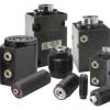
Metric Swing Clamps Standard
Features
|
U.S. Patent Nos. |

Patented V-groove Cam Design
|
 |
Standard Metric Swing Clamps, Threaded Body
Specifications
|
|
|
||||||||||||||||||||||||||||||||||||||||||||||||||||||||||||||||||||||||||||||||||||||||||||||||||||||||||||||||||||||||||||||||||||||
|
|||||||||||||||||||||||||||||||||||||||||||||||||||||||||||||||||||||||||||||||||||||||||||||||||||||||||||||||||||||||||||||||||||||||
|
WARNING! Never allow swing arm to contact workpiece or fixture during rotation. * Cylinder capacities are listed at 350 bar (35 MPa) maximum operating pressure with a standard VektorFlo®arm installed. See the Arm Length and Pressure Limitations graph for clamping force with various other arm lengths installed. The clamping force is adjustable by varying the hydraulic system pressure. To determine the approximate output force for your application, divide the cylinder capacity shown above by 350 bar (35 MPa), and multiply the resultant number times your system operating pressure to obtain the approximate clamping force for your application. (Actual force will vary slightly due to internal cantilever loading, friction loss, and/or return springs.) ** To allow for piece part height variations, it is recommended that the vertical travel be set at about 50% of the vertical stroke. *** To insure maximum service life and trouble-free operation, restrict fluid flow to the level indicated in theClamp Time and Fluid Flow Rate chart. |
 |
||||||||||||||||||||||||||||||||||||||||||||||||||||||||||||||||||||||||||||||||||||||||||||||||||||||||||||||||||||||||||||||||||||||

Standard Metric Swing Clamps, Threaded Body, Long Stroke
Specifications
|
|
 |
|||||||||||||||||||||||||||||||||||||||||||||||||
|
||||||||||||||||||||||||||||||||||||||||||||||||||
|
WARNING: Never allow swing arm to contact workpiece or fixture during rotation. * Cylinder capacities are listed at 350 bar (35 MPa) maximum operating pressure with a standard VektorFlo® arm installed. See the Arm Length and Pressure Limitations graph for clamping force with various other arm lengths installed.The clamping force is adjustable by varying the hydraulic system pressure. To determine the approximate output force for your application, divide the cylinder capacity shown above by 350 bar (35 MPa), and multiply the resultant number times your system operating pressure to obtain the approximate clamping force for your application. (Actual force will vary slightly due to internal cantilever loading, friction loss, and/or return spring.) NOTETo allow for piece part height variations, it is recommended that the vertical travel be set at about 50% of the vertical stroke. NOTE:To insure maximum service life and trouble-free operation, restrict fluid flow to the level indicated in the Clamp Time and Fluid Flow Rate chart. |
|
|||||||||||||||||||||||||||||||||||||||||||||||||
Standard Metric Swing Clamp, Top Flange/Manifold Mount
Specifications
 |
 |
||||||||||||||||||||||||||||||||||||||||||||||||||||||||||||||||||||||||||||||||||||||||||||||||||||||||||||||||||||||||||||
|
|||||||||||||||||||||||||||||||||||||||||||||||||||||||||||||||||||||||||||||||||||||||||||||||||||||||||||||||||||||||||||||
|
WARNING: Never allow swing arm to contact workpiece or fixture during rotation. Cylinder capacities are listed at 350 bar (35 MPa) maximum operating pressure with a standard VektorFlo® arm installed. See the Arm Length and Pressure Limitations graph for clamping force with various other arm lengths installed. The clamping force is adjustable by varying the hydraulic system pressure. To determine the approximate output force for your application, divide the cylinder capacity from the graph by 350 (35 MPa), and multiply the Resultant Number times Your System Operating Pressure to obtain the approximate clamping force for your application. Actual force will vary slightly due to internal cantilever loading, friction loss and/or return springs. ** To allow for piece part height variations, it is recommended that the vertical travel be set at about 50% of the vertical stroke. NOTE: To insure maximum service life and trouble-free operation, restrict fluid flow to the level indicated in theClamp Time and Fluid Flow Rate chart. |
|
||||||||||||||||||||||||||||||||||||||||||||||||||||||||||||||||||||||||||||||||||||||||||||||||||||||||||||||||||||||||||||
Standard Metric Swing Clamp, Manifold/Bottom Flange Mount
Specifications
 |
 |
|||||||||||||||||||||||||||||||||||||||||||||||||||||||||||||||||||||||||||||||||||||||||||||||||||||||||||||||||||||
|
||||||||||||||||||||||||||||||||||||||||||||||||||||||||||||||||||||||||||||||||||||||||||||||||||||||||||||||||||||||
|
WARNING: Never allow swing arm to contact work piece or fixture during rotation. * Cylinder capacities are listed at 350 bar (35 MPa) maximum operating pressure, with a standard length VektorFlo® arm installed. Minimum operating pressure is 52 bar (5,2 MPa) for single acting, 35 bar (3,5 MPa) for double acting. The clamping force is adjustable by varying the hydraulic system pressure. To determine the approximate output force for your application, divide the cylinder capacity shown above by 5,000, and multiply the Resultant Number X Your System Operating Pressure to obtain the approximate clamping force for your application. (Actual force will vary slightly due to internal cantilever loading, friction loss and/or return springs.) ** To allow for piece part height variations, it is recommended that the vertical travel be set at about 50% of the vertical stroke. *** To ensure maximum service life and trouble-free operation, restrict fluid flow per Clamp Time and Fluid Flow Rates Table |
|
|||||||||||||||||||||||||||||||||||||||||||||||||||||||||||||||||||||||||||||||||||||||||||||||||||||||||||||||||||||
81-5505-45
81-5505-60
81-5518-60
81-5518-45
81-5513-60
81-5513-45
81-5509-60
81-5509-45
81-5513-30
81-5505-30
81-5509-30
81-5518-30
81-5519-30
81-5519-45
81-5519-60
81-5522-30
81-5522-45
81-5522-60
41-5002-11
41-5002-12
41-5002-21
41-5002-22
41-5005-11
41-5005-12
41-5005-21
41-5005-22
41-5011-11
41-5011-12
41-5011-21
41-5011-22
41-5022-11
41-5022-12
41-5022-21
41-5022-22
41-5605-15
41-5002-15
41-5002-25
41-5005-15
41-5005-25
41-5011-15
41-5011-25
41-5022-15
41-5022-25
41-5005-23
41-5005-24
41-5011-23
41-5011-24
41-5005-26
41-5011-26
41-5602-11
41-5602-12
41-5602-21
41-5602-22
41-5605-11
41-5605-12
41-5605-21
41-5605-22
41-5611-11
41-5611-12
41-5611-21
41-5611-22
47-0203-71
47-0203-74
41-5605-15
41-5602-15
41-5602-25
41-5605-25
41-5611-15
41-5611-25
41-5202-11
41-5202-12
41-5202-21
41-5202-22
41-5205-11
41-5205-12
41-5205-21
41-5205-22
41-5211-11
41-5211-12
41-5211-21
41-5211-22
47-0203-71
47-0203-74
41-5202-15
41-5202-25
41-5205-15
41-5205-25
41-5211-15
41-5211-25