Sign In


E-Catalog > miniBOOSTER > HC4 miniBOOSTER
Product Detail :
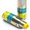
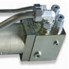
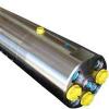
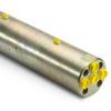
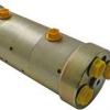
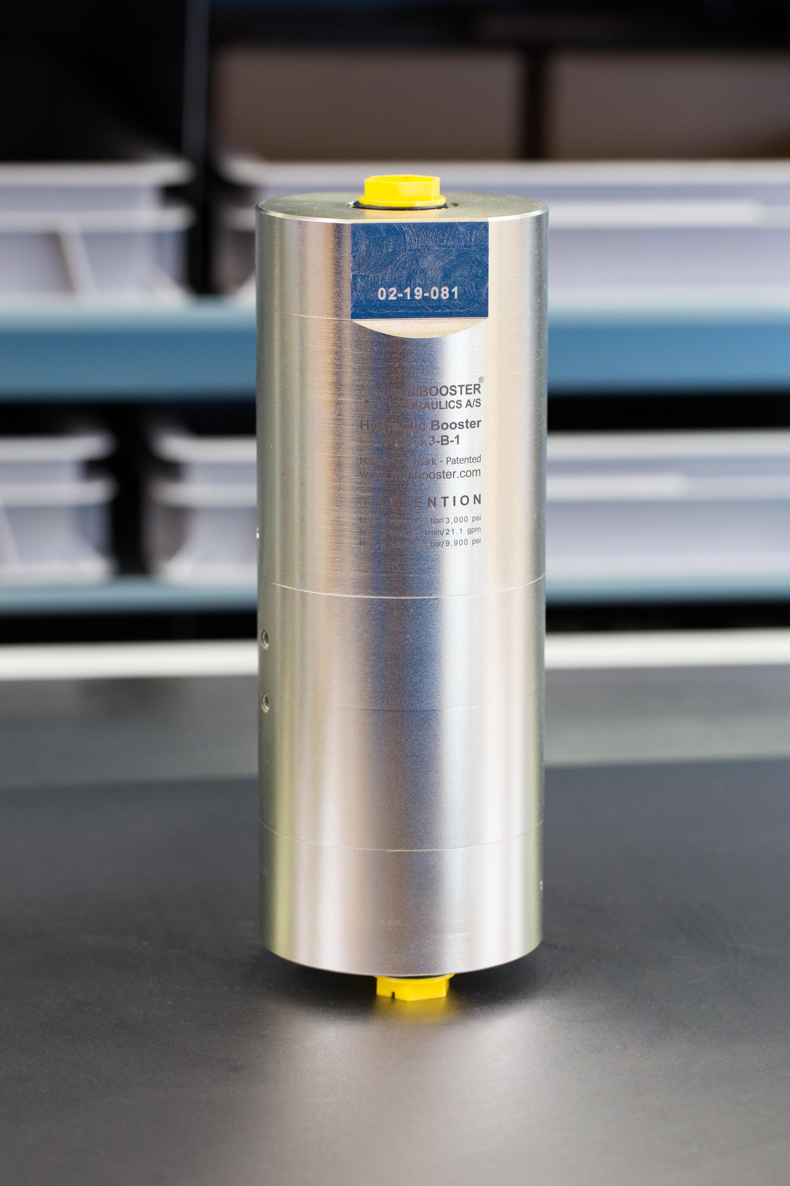
The HC4 miniBOOSTER

HC4 versions: 9 different intensification factors
PIN: 20 – 200 bar (inlet pressure)
PH: 800 bar maximum (outlet pressure)
PRETURN: As low as possible (Return pressure to tank)
Intensification ratios: PH = (PIN – PReturn) i (Intensification)
Mounting: Inline tube
Accessories: Pilot operated dump valve available
A model = no dump valve
B model = with dump valve
G model = direct proportionally controlled
Description
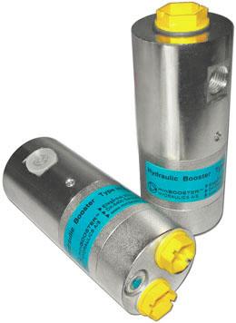
The HC4 is ideal for use in applications where a higher volume of high pressure fluid is required. The HC4 is a compact unit weighing only 3.7 kg, but it delivers up to 5.0 liters/min. outlet flow. Like the HC2, it raises supplied pressure and automatically compensates for consumption of oil to maintain the high pressure. Adjustment of the outlet pressure is carried out by varying the supplied pressure.
Flow Rates
|
Intensification factor |
Max. outlet flow |
Max. inlet flow |
|---|---|---|
|
1.3 |
1.5 |
25.0 |
|
1.8 |
1.2 |
25.0 |
|
2.1 |
7.0 |
35.0 |
|
2.8 |
6.0 |
35.0 |
|
3.2 |
5.0 |
35.0 |
|
4.3 |
4.0 |
35.0 |
|
5.1 |
3.5 |
35.0 |
|
6.3 |
2.5 |
35.0 |
|
9.8 |
2.0 |
35.0 |
Dimensions

Functions
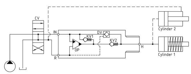
The basic operation is illustrated in the function diagram. Oil is fed through the directional valve CV to the IN port, flowing freely through the check valves KV1, KV2 and DV to the high pressure side H. In this condition maximum flow through the booster is achieved giving a fast forward function.
When pump pressure is reached on the high pressure side H, valves KV1, KV2 and DV will close. The end pressure will be achieved by the oscillating pump unit OP. The unit will automatically stall when end pressure on high pressure side H is reached. If there is a pressure drop on the high pressure side due to consumption or leakage, the OP valve will automatically operate to maintain the end pressure.
Function Diagram

Connection types
|
Connection |
IN / R |
H |
|---|---|---|
|
1 |
3/8" BSP |
1/2" BSP |
|
2 |
9/16-18 UNF |
3/4-16 UNF |
Max. tightening torque BSP
|
IN / R |
H | |
|---|---|---|
|
3/8" BSP |
1/2" BSP |
|
|
with steel washer |
6.0 da/Nm |
13.0 da/Nm |
|
with aluminium washer |
4.0 da/Nm |
– |
|
with cutting edge |
6.0 da/Nm |
13.0 da/Nm |
Max. tightening torque UNF
|
IN / R |
H | |
|---|---|---|
|
9/16-18" UNF |
3/4-16" UNF |
|
|
with o-ring |
3.5 da/Nm |
6.0 da/Nm |
Fluids and materials
Please see General Specifications
Ordering a HC4
Ordering example of a HC4 with i = 4.3, DV incorporated and BSP connections: HC4 - 4.3 - B - 1
|
Model |
Intensification, i |
Dump Valve |
Connections |
|||
|
HC4 |
your selection... |
your selection... |
your selection... |
|||
|
see flow rate table |
A = (no) / A model |
1 |
||||
|
B = (yes) / B model |
2 |
|||||
|
G = (proportional) / G model |
||||||
HC3
Data:
HC3 versions: 15 different intensification factors
PIN: 20–207 bar
PH: 500 bar maximum
PRETURN: As low as possible (return pressure to tank)
POUTLET: PH = (PIN – PRETURN) x intensification factor
Mounting: NG6 (D03) stacking manifold system
Weight: 2.5 kg.
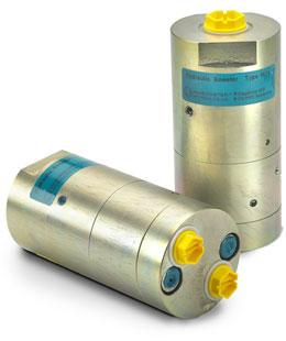
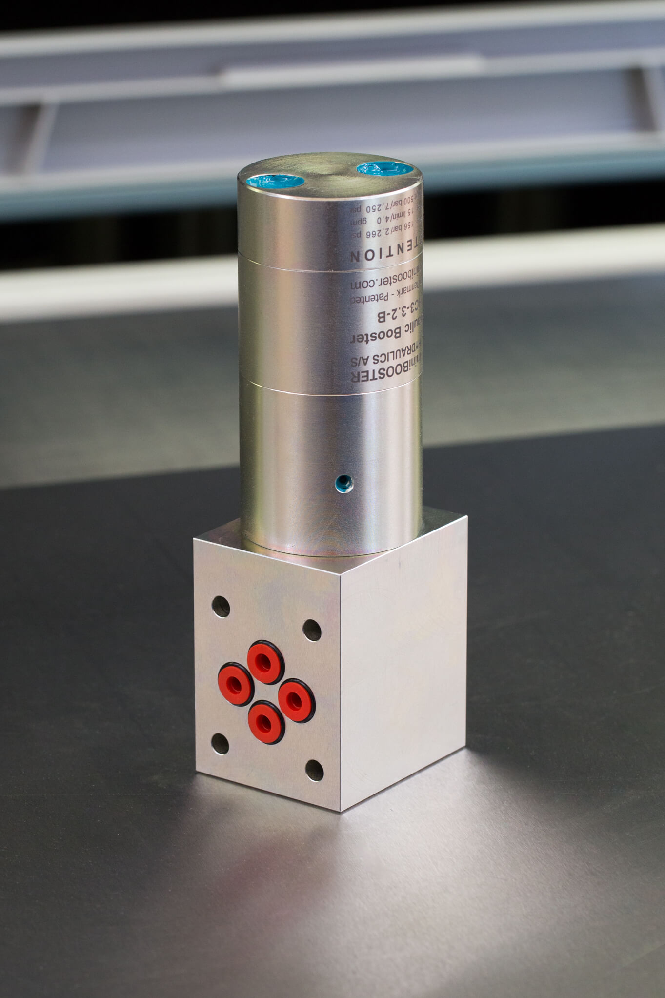
Description
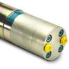
The HC3 is a version of the HC2 designed for use in NG6 (D03) stacking manifold systems. It is a compact unit weighing only 2.5 kg.
Maximum outlet pressure is 500 bar in standard versions. Adjustments of the outlet pressure is carried out by varying the supplied pressure.
Flow rates
| Intensification factor i | Max. intensified outlet flow l/min | Max. inlet flow l/min |
|---|---|---|
| 1.2 | 3.5 | 8.0 |
| 1.5 | 4.2 | 12.0 |
| 2.0 | 3.2 | 12.0 |
| 2.2 | 2.9 | 12.0 |
| 2.5 | 2.7 | 13.0 |
| 2.8 | 2.5 | 13.0 |
| 3.2 | 2.5 | 15.0 |
| 4.0 | 2.0 | 14.0 |
| 5.0 | 1.6 | 14.0 |
| 6.6 | 1.3 | 13.0 |
| 9.0 | 0.9 | 13.0 |
| 13.0 | 0.6 | 12.0 |
| 16.0 | 0.5 | 12.0 |
| 20.0 | 0.3 | 12.0 |
| 25.0 | 0.2 | 12.0 |
Functions
The basic operation is illustrated in the function diagram. The oil is fed through the connecting plate to the control valve to the IN port of the HC3 flowing freely through check valves KV1, KV2 and DV to the high pressure side H.
From the high pressure side H oil is fed to port A on the connecting plate. In this condition maximum flow through the booster is achieved giving a fast forward function. When pump pressure is reached on the high pressure side H, valves KV1, KV2 and DV will close. The end pressure will be achieved by the oscillating pump unit OP. The unit will automatically stall when end pressure on high pressure side is reached. If there is a pressure drop on the high pressure side due to consumption or leakage, the OP valve will automatically operate to maintain the end pressure.
Function diagram
3-105-00

Dimensions
Dimension drawing 3-120-04
HC1
Data:
HC1 versions: 9 different intensification factors
PIN: 20–207 bar
PH: 800 bar maximum
PRETURN: As low as possible (return pressure to tank)
POUTLET: PH = (PIN – PRETURN) x intensification factor
Mounting: Inline tube
Weight: 0.7 kg.
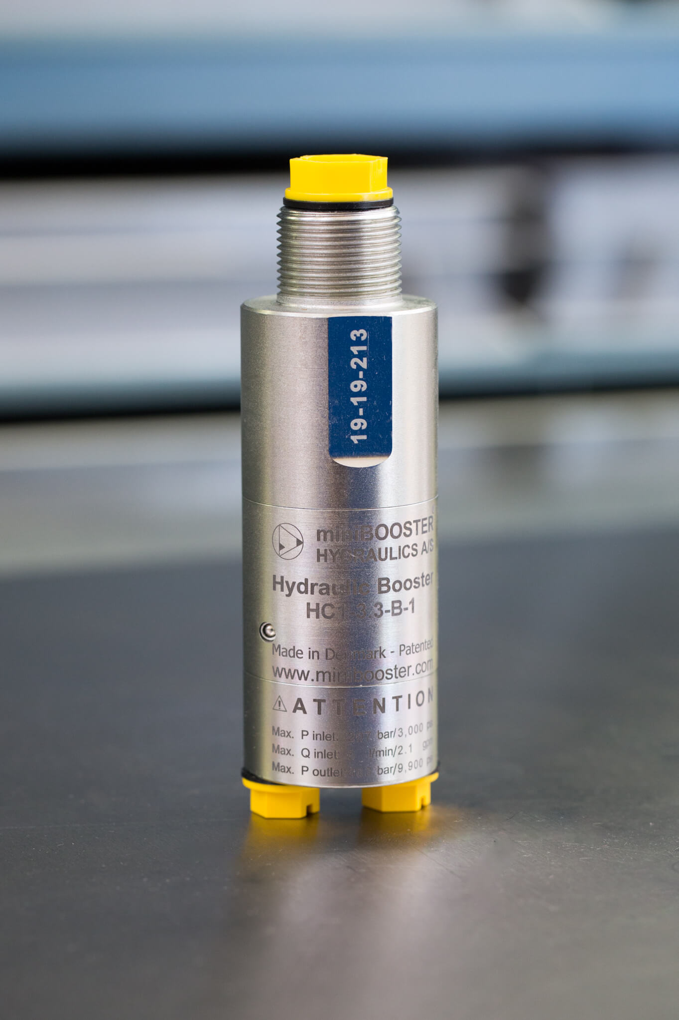
Description
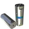
The HC1 is the most compact miniBOOSTER unit weighing only 0.7 kg. It is ideal for use in applications where it is desirable to mount the unit on or in a tool, power pack, or other device.
The HC1 raises supplied pressure to a higher outlet pressure and automatically compensates for consumption of oil to maintain the high pressure. Adjustment of the outlet pressure is carried out by varying the supplied pressure.
Flow rates
| Intensification factor i | Max. intensified outlet flow l/min | Max. inlet flow l/min |
|---|---|---|
| 1.2 | 3.0 | 8.0 |
| 1.5 | 2.8 | 8.0 |
| 2.0 | 2.1 | 8.0 |
| 2.8 | 1.5 | 8.0 |
| 3.3 | 1.3 | 8.0 |
| 4.0 | 1.1 | 8.0 |
| 4.8 | 0.9 | 8.0 |
| 6.2 | 0.7 | 8.0 |
| 7.5 | 0.5 | 8.0 |
Functions
The basic operation is illustrated in the function diagram. Oil is fed through the directional valve CV to the IN port, flowing freely through the check valves KV1, KV2 and DV to the high-pressure side H. In this condition maximum flow through the booster is achieved, giving a fast-forward function.
When pump pressure is reached on the high-pressure side H, valves KV1, KV2 and DV will close. The end pressure will be achieved by the oscillating pump unit OP. The unit will automatically stall when end pressure on the high-pressure side H is reached. If a pressure drop on the high-pressure side exists due to consumption or leakage, the OP valve will automatically operate to maintain the end pressure.
Function diagram
1-105-01
Dimensions
Dimension drawing 1-120-04
HC6
Data:
HC6 versions: 9 different intensification factors
PIN: 20 – 207 bar
PH: 800 bar maximum
PRETURN: As low as possible (return pressure to tank)
POUTLET: PH = (PIN – PRETURN) x intensification factor
Mounting: Inline tube
Weight: 9.5 kg.
Description
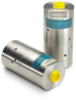
The HC6 is a high-flow unit which is capable of delivering up to 28.3 l/min flow on the high-pressure end.
Like other miniBOOSTER models, the HC6 raises supplied pressure to a higher outlet pressure and automatically compensates for consumption of oil to maintain the high pressure. Adjustment of the outlet pressure is carried out by varying the supplied pressure. Relative to its flow capability, the HC6 is a compact unit weighing only 9.5 kg.
Flow rates
| Intensification factor i | Max. intensified outlet flow l/min | Max. inlet flow l/min |
|---|---|---|
| 1.3 | 20.3 | 50.0 |
| 1.5 | 28.3 | 80.0 |
| 1.9 | 22.3 | 80.0 |
| 2.5 | 17.0 | 80.0 |
| 3.3 | 12.8 | 80.0 |
| 4.0 | 10.6 | 80.0 |
| 4.9 | 8.6 | 80.0 |
| 6.3 | 6.7 | 80.0 |
| 8.2 | 5.2 | 80.0 |
miniBOOSTER miniBOOSTER miniBOOSTER miniBOOSTER miniBOOSTER miniBOOSTER miniBOOSTER miniBOOSTER miniBOOSTER miniBOOSTER miniBOOSTER miniBOOSTER miniBOOSTER miniBOOSTER miniBOOSTER miniBOOSTER miniBOOSTER miniBOOSTER miniBOOSTER miniBOOSTER miniBOOSTER miniBOOSTER miniBOOSTER miniBOOSTER