Sign In


Product Detail :
ntroduction to Face Driving
- How a Face Driver Works
- How to Select a Face Driver
- Confused? Let Riten Select Your Driver
- Face Driver Application Example
Ever increasing demands on the manufacturer to improve productivity and quality have led to the need for faster machining techniques. Face drivers, along with today’s new high performance equipment, let you maximize your production capabilities for minimal expense.
With a Riten USA Face Driver, the entire workpiece is exposed for machining. Therefore, you are able to machine the entire length of the workpiece in one operation. The elimination of a setup in the production process results in increased accuracy and efficiency. Furthermore, the single axis reference point established by the center point of the face driver allows for a higher concentricity.
The Riten USA Face Driver Line consists of seven hydraulic designs and ten mechanical designs. There is a face driver available for your specific application.
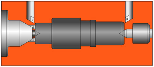
Face Driving Long, Small Diameter Parts
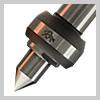
How A Face Driver Works
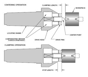
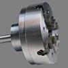
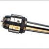
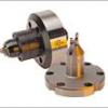
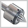
A face driver has two main components, the drive head and the mounting. The mounting locates the driver in the machine with either a morse taper shank mount directly into the machine taper; or a chuck mount chucked between special chuck jaws; or a flange mount bolted to a spindle adapter on the machine spindle. The illustration shows a morse taper shank. The drive head (also known as a carrier body) contains the compensating medium (hydraulic or mechanical); which allows the pins to adjust to variations in the locating face and the spring-loaded center point. Face driving is a simple two step clamping operation, centering followed by clamping. Under tailstock pressure, the workpiece engages the center point which locates the part and provides a consistent axis of rotation. As the tailstock continues to drive the workpiece against the center point, the axial pressure forces the spring-loaded center point back into the carrier body until the drive pins engage the face of the workpiece. Each pin individually compensates for any irregularities in the face until all of the pins are fully engaged. Under the increasing axial load, the drive pins penetrate the workpiece completing the clamping operation, while the center point maintains the axis of rotation.
The compensating medium (either hydraulic or mechanical) in the face driver assures equal penetration of the drive pins despite variations in the surface or in the squareness of the face. Therefore, surface imperfections or out of square saw cuts do not present a problem when face driving.
Five Misconceptions about Face Driving
How to Select a Face Driver
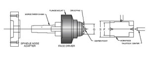
1. Determine the finish diameter (F) of the workpiece at the driving face.
2. Choose the face driver series whose maximum driving diameter (G) is smaller than the finish diameter (F).
3.(G) should be .020 smaller than (F) to allow for clearance.
4.Check the maximum raw stock size (S). (S) should not be more than three times (G) for maximum gripping capabilities. If you require a larger maximum raw bar stock size, please contact Riten technical supportm.kirby@riten.com
5. Determine the rotation of the headstock to determine drive pin direction. See diagram below:
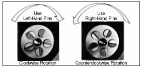
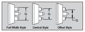
6.Choose the drive pins that allow maximum driving diameter (G). Full width drive pins are the first choice for maximum gripping force.
However, offset, half offset drive pins are also available to meet a broad range of part diameters. See diagram below:
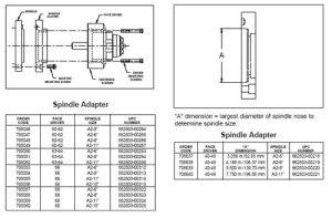
7. Choose the mounting styles (taper
Mount, flange and chuck mount) that are available for each Series of face drivers. If you choose a flange mount and plan to mount the driver directly to the spindle of the machine a spindle adapter will be required. See diagrams below:
Face Driving Fundamentals
Back to Basics
The Fundamentals of Face Driving
In a world where success is determined by the bottom line, manufacturers are always researching and developing new ways to cut costs and increase production. Whether it’s at the grinding wheel or the CNC lathe, plant managers are always looking to get the most out of their tooling. This need for progress and innovation has lead to many new developments in workholding, including the engineering of high precision face drivers.
Though not a new concept, face driving has been gaining ground in the manufacturing industry as a cost effective way for machinists to hold any type of cylindrical work piece during turning.
In a typical turning application, a machinist chucks one end of the metal workpiece and begins his cut. As he nears completion of the available area, he is forced to stop the machine and turn the part around to complete the cutting of the surface that was previously in the chuck jaws. This process creates two problems. The first and most obvious issue is the time involved. When running production quantities in the hundreds or thousands, the time it takes to chuck each part twice quickly adds up and begins to cut into profits. The second problem lays in the concentricity of the finished piece. If a manufacturer is producing axles or a similar type of shaft work, it is very important that the dimensions of the part be precise from end to end. However, these dimensions may vary slightly in this type of manufacturing process, as the workpiece may not be perfectly aligned when it is chucked for the second time. Both of these problems can be eliminated with the use of a face driver.
A face driver does away with the need to flip the workpiece during the production process and allows for the entire piece to be worked in one operation. In this process the piece of steel is centered in the machine using a live center that locates its point in the center hole on one end of the workpiece. A face driver then uses tailstock pressure to engage the workpiece with its center point which locates the part and provides a consistent axis of rotation. As the machine’s tailstock pressure continues to drive the workpiece against the center point, the axial pressure forces the spring-loaded center point back into the carrier body until the drive pins engage the face of the workpiece, eliminating the need to chuck on the outer diameter. Each pin individually compensates for any irregularities in the face until all pins are fully engaged. This technique removes the chuck jaws from the path of the cutting tool and enables the piece to be worked from end to end, simultaneously cutting production time and increasing concentricity.
Nomenclature
- A face driver is made up of four main parts and is available in two designs and three different mounting options.
- Flange/Shank: The lower portion of the face driver which mounts into the machine and houses many of the internal mechanical parts.
- Carrier Body: Serves as the guide and housing for the drive pins, center points, and compensating medium.
- Center Point: A replaceable spring loaded point that locates in the center hole of the workpiece and provides an axis of rotation while enabling the drive pins to engage the face.
- Drive Pins: Act as the teeth of the face driver and bite into the face of the part being machined. Drive pins are replaceable and depending on the size of the driver and the workpiece involved are used in sets of three to ten.
- Mechanical Face Drivers: The driving pins move independently to allow a five degree pitch of the end face of the workpiece. The mechanical compensation and lock down center point allow a constant length to be held from the center to the taper.
- Hydraulic Face Drivers: This design is generally used in medium roughing operations and can handle loads of up to 3,000 pounds. The pressure equalization of the driving pins is provided by hydraulic fluid. This permits a seven degree pitch on the end face of the part. Behind every drive pin is a sealed piston that prevents oil leakage. The oil cavities behind the pistons are interconnected and the whole system is enclosed.
- Shank Mount: Used when machine spindle requires a morse taper mount.
- Chuck Mount: Shank is gripped using chuck jaws.
- Flange Mount: With a spindle adapter this design mounts directly to the machine. A Flange mount is the most rigid mounting procedure and enables manufacturers to hold high tolerances.
Mounting
Mounting a Mechanical Face Driver
- Before mounting, indicate on the face of the machine spindle to verify the accuracy of the machine bearings and spindle face.
- Mount the spindle adapter onto the machine spindle with the adapter mounting screws. Indicate on the spindle adapter face where the face driver will be mounted. Make adjustments if necessary to achieve approximately .005mm (.0002″) run out or less. This number can vary depending on machine variables and the degree of accuracy that you are trying to achieve.
- Lightly tap the inner ring onto the face driver with a plastic mallet. Take care to make sure the inner ring remains straight while being mounted. The inner ring should be flush with the back of face driver when correctly assembled.
- Mount the face driver to the spindle adapter with the face driver mounting screws. Snug the screws, but do not tighten. Indicate on the center point nose angle (usually a 60 degree nose angle) or on the ID bore where the center point is mounted. Make adjustments with the centering screws if necessary to achieve approximately .008mm (.0003″) run out or less. This number can vary depending on machine variables and the degree of accuracy that you are trying to achieve. IMPORTANT! Remember to tighten the driver mounting screws to lock the face driver in place before use.
Mounting a Hydraulic Face Driver
- Before mounting, indicate on the face of the machine spindle to verify the accuracy of the machine bearings and spindle face.
- Mount the spindle adapter onto the machine spindle with the adapter mounting screws. Indicate on the spindle adapter face where the face driver will be mounted. Make adjustments if necessary to achieve approximately .005mm (.0002″) run out or less. This number can vary depending on machine variables and the degree of accuracy that you are trying to achieve.
- Mount the face driver to the spindle adapter with the face driver mounting screws. Snug the screws, but do not tighten. Indicate on the center point nose angle (usually a 60 degree nose angle) or on the ID bore where the center point is mounted. Make adjustments with the centering screws if necessary to achieve approximately .008mm (.0003″) run out or less. This number can vary depending on machine variables and the degree of accuracy that you are trying to achieve. IMPORTANT! Remember to tighten the driver mounting screws to lock the face driver in place before use.