Sign In


E-Catalog > miniBOOSTER > The HC7 miniBOOSTER
Product Detail :
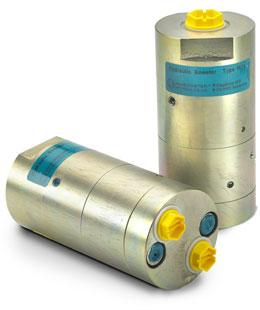
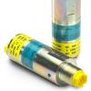
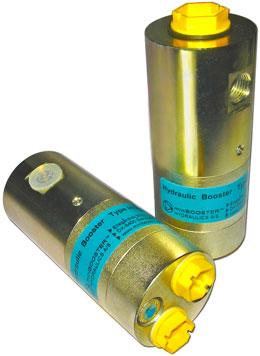
The HC7 miniBOOSTER

HC7 versions: 5 different intensification factors
PIN: 20 – 200 bar (inlet pressure)
PH: 2000 bar maximum (outlet pressure)
PRETURN: As low as possible (Return pressure to tank)
Intensification ratios: PH = (PIN – PReturn) i (Intensification)
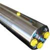
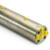
Mounting: Inline tube
Accessories: Pilot operated dump valve incorporated
A model = no dump valve
B model = with dump valve
G model = direct proportionally controlled
Description
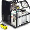
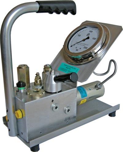
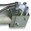
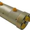
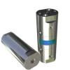
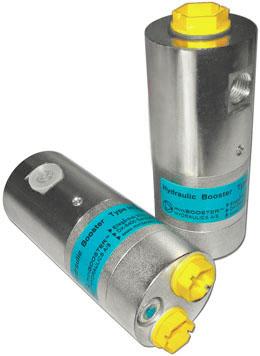
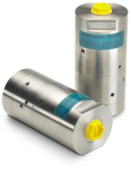
The HC7 is a very compact high pressure unit capable of delivering pressure up to 2,000 bar with a weight of only 1.5 kg. It is ideal for use in portable applications like on power packs.
The HC7 raises supplied pressure to a higher outlet pressure and automatically compensates for consumption of oil to maintain the high pressure. Adjustment of the outlet pressure is carried out by varying the supplied pressure. With the choice of different high pressure adapters a variety of threads can be obtained from the M22x1.5 thread in the HP port. Higher pressure is available on request.
Flow Rates
|
Intensification factor |
Max. outlet flow |
Max. inlet flow |
|---|---|---|
|
5.0 |
1.6 |
14.0 |
|
6.6 |
1.3 |
13.0 |
|
9.0 |
0.9 |
13.0 |
|
13.0 |
0.6 |
12.0 |
|
20.0 |
0.3 |
12.0 |
Dimensions

Functions
The basic operation is illustrated in the function diagram. Oil is fed through the directional valve CV to the IN port, flowing freely through the check valves KV1, KV2 and DV to the high pressure side H. In this condition maximum flow through the booster is achieved giving a fast forward function.
When pump pressure is reached on the high pressure side H, valves KV1, KV2 and DV will close. The end pressure will be achieved by the oscillating pump unit OP. The unit will automatically stall when end pressure on high pressure side H is reached. If there is a pressure drop on the high pressure side due to consumption or leakage, the OP valve will automatically operate to maintain the end pressure.
Function Diagram

Connection types
|
Connection |
IN / R |
|---|---|
|
1 |
1/4" BSP |
|
2 |
7/16-20" UNF |
Max. tightening torque BSP
|
IN / R | |
|---|---|
|
1/4" BSP |
|
|
with steel washer |
4.0 da/Nm |
|
with aluminium washer |
3.0 da/Nm |
|
with cutting edge |
4.0 da/Nm |
Max. tightening torque UNF
|
IN / R | |
|---|---|
|
7/16-20" UNF |
|
|
with o-ring |
2.0 da/Nm |
High pressure adapters
|
Ordering Code |
Male connection 1 |
Connection 2 |
|---|---|---|
|
7-432 |
M22 x 1.5 |
9/16-18 UNF |
|
7-433 |
M22 x 1.5 |
1/4" BSP |
|
7-434 |
M22 x 1.5 |
Plug |
|
7-435 |
M22 x 1.5 |
1/4" BSP |
|
7-439 |
M22 x 1.5 |
9/16-18 UNF |
|
7-445 |
M22 x 1.5 |
1/4" BSP male |
|
7-446 |
M22 x 1.5 |
M22 x 1.5 |

Fluids and materials
Please see General Specifications
Ordering a HC7
Ordering example of a HC7 with i = 13.0, H1 M22 x 1.5 and H2 9/16-18 UNF,
DV incorporated and BSP connections: HC7 - 13.0 - B - 12
Please note!
High pressure adapter ordering code – see table
|
Model |
Intensification, i |
Dump Valve |
Connections | |||
|---|---|---|---|---|---|---|
|
HC7 |
your selection... |
your selection... |
see table below |
|||
|
see flow rate table |
A = (no) / A model |
|||||
|
B = (yes) / B model |
||||||
|
G = (proportional) / G model |
||||||
|
Ordering Code |
IN, R |
H1 |
H2 |
H3 |
|---|---|---|---|---|
|
HC7-___-__-11 |
1/4" BSP |
M22 x 1.5 |
– |
– |
|
HC7-___-__-21 |
7/16-20 UNF |
M22 x 1.5 |
– |
– |
|
HC7-___-__-12 |
1/4" BSP |
M22 x 1.5 |
9/16-18 UNF |
– |
|
HC7-___-__-22 |
7/16-20 UNF |
M22 x 1.5 |
9/16-18 UNF |
– |
|
HC7-___-__-13 |
1/4" BSP |
M22 x 1.5 |
9/16-18 UNF |
9/16-18 UNF |
|
HC7-___-__-23 |
7/16-20 UNF |
M22 x 1.5 |
9/16-18 UNF |
9/16-18 UNF |