Sign In


BT spindle test bar BT pulling force
BT spindle test bar BT pulling force

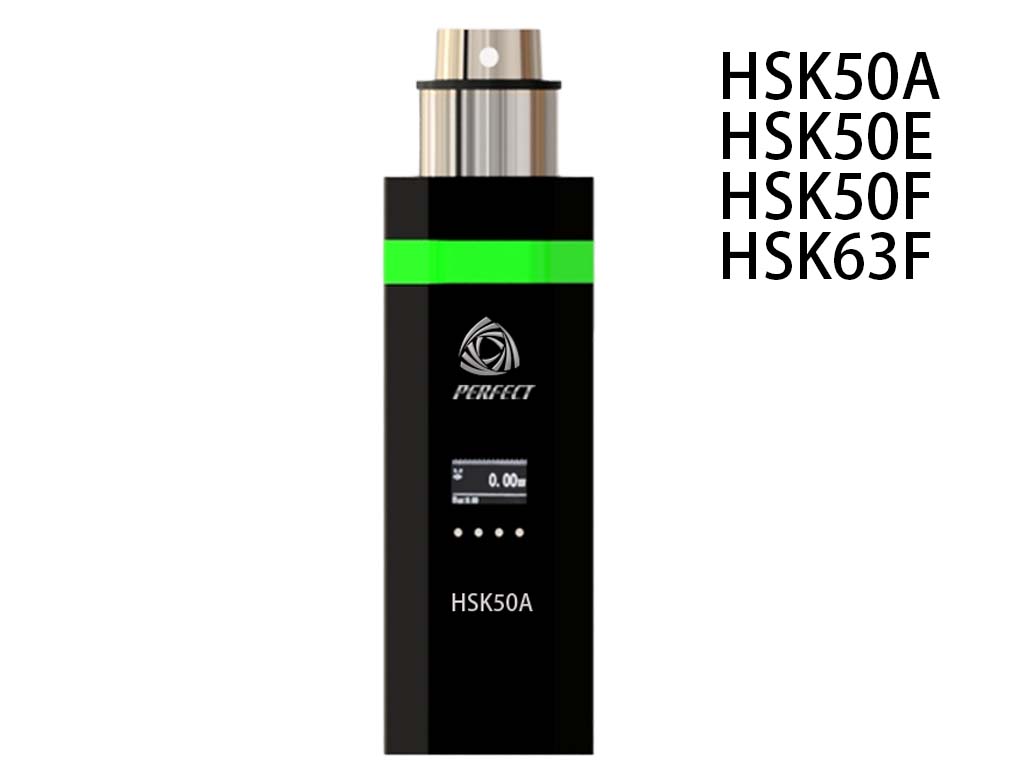
XXRT-HSK50 XXR-HSK50 spindle tension meter

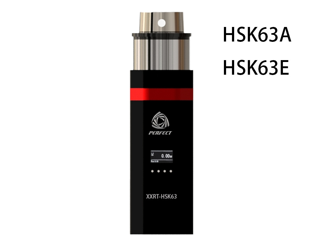
XXRT-HSK63A HSK63 spindle tension meter

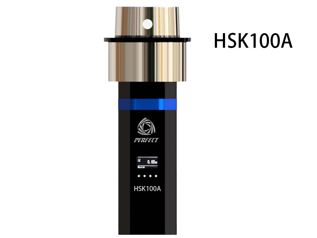
XXRT-HSK100 XXRT-HSK100A

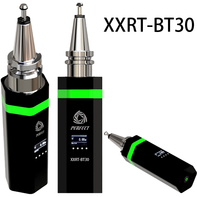
XXRT BT30 XXRT BT30 spindle tension meter digital display
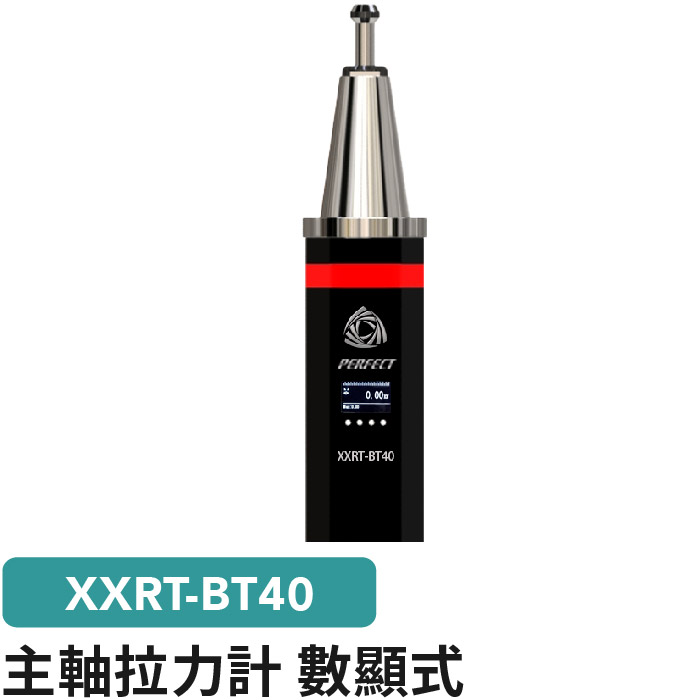
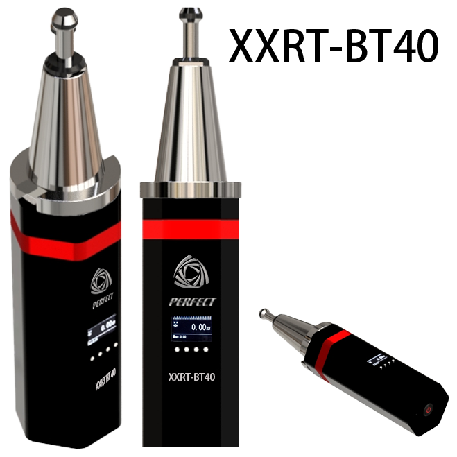
XXRT BT40 XXRT BT40 spindle tension meter digital display

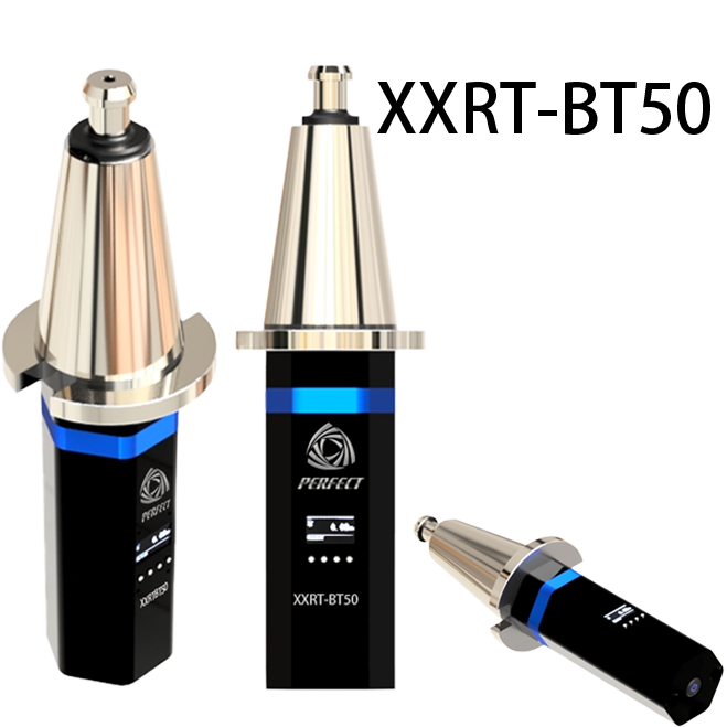
XXRT BT50 XRT BT50????? ??? spindle tension meter digital display
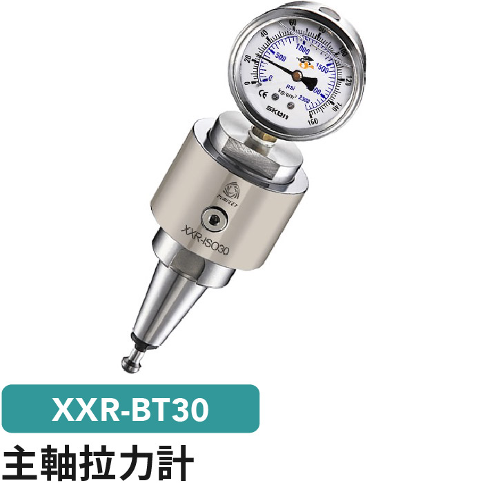
XXR-BT30 Spindle Force Dynamometer
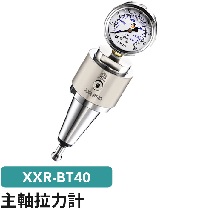
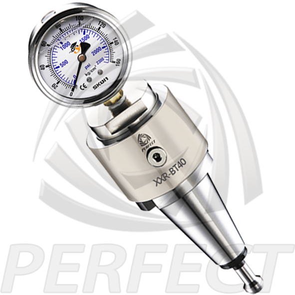
XXR-BT40 Spindle Force Dynamometer
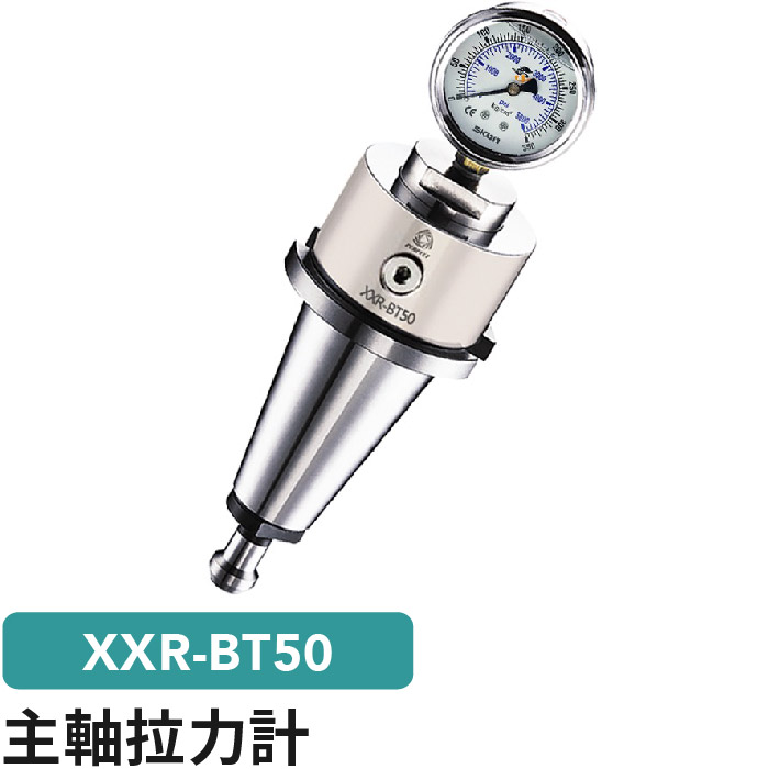
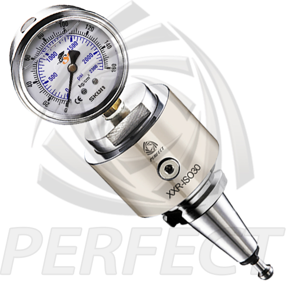
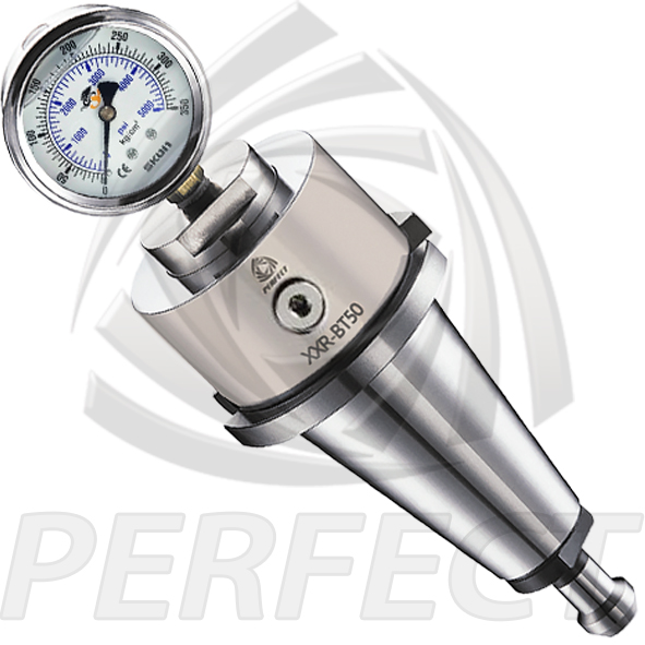
XXR-BT50 XXR-ISO Clamping Force Gauge

XXRG Digital Spindle Force Dynamometer
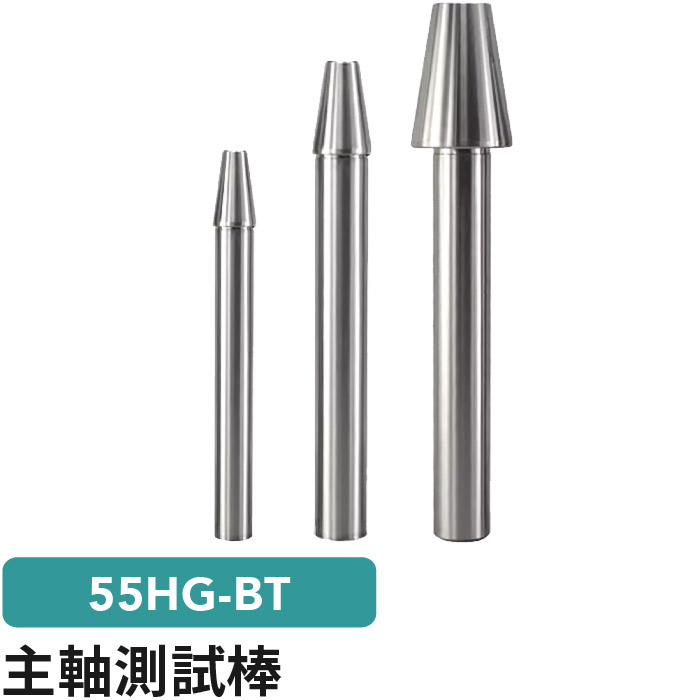
55HG-BT 55HG Test Bar BT
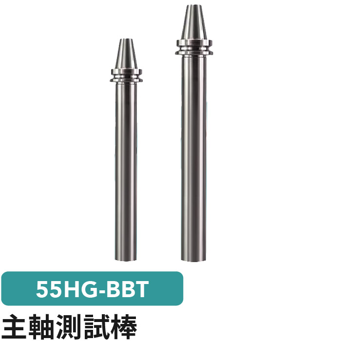
55HG 55HG BBT Test Bar
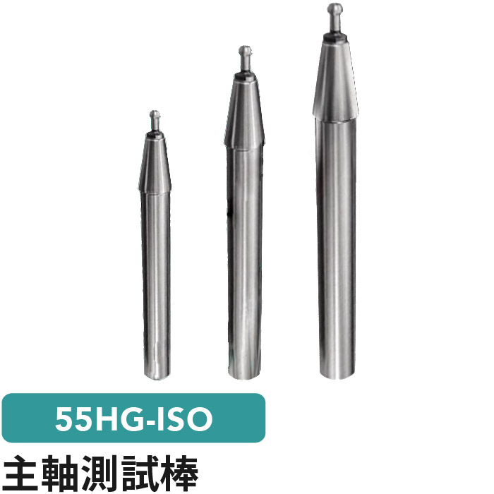
55HG ISO Test Bar
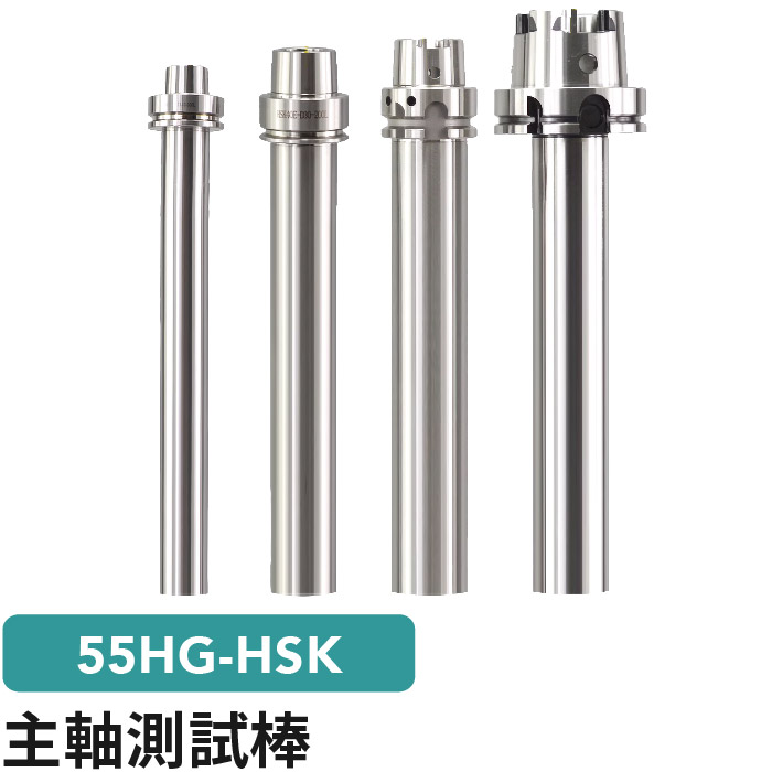
55HG 55HG Test Bar HSK

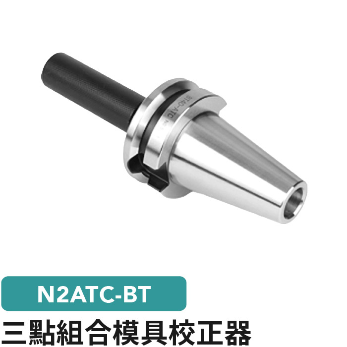
N2ATC N2ATC triple test bar
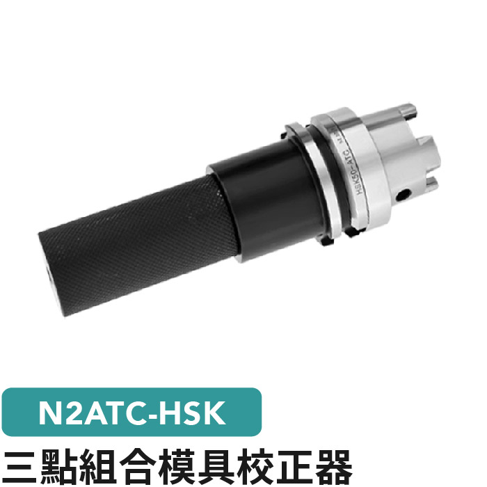
N2ATC N2ATCHSK ???? triple test bar
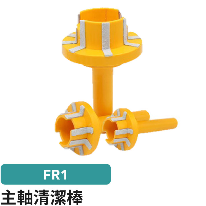
FR1 Spindle cleaning rod
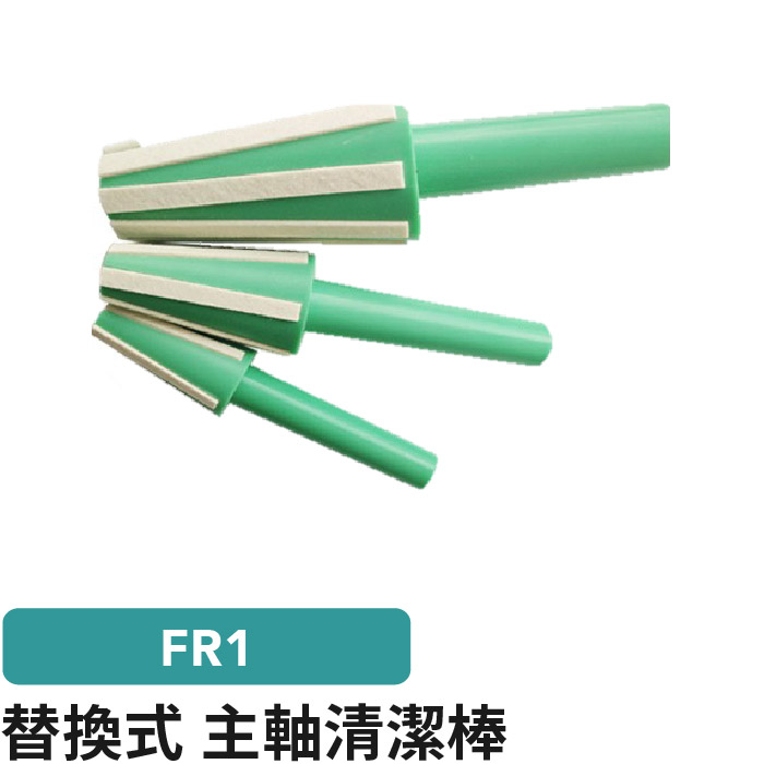
FR1 Spindle cleaning rod
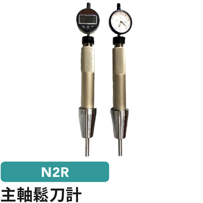
N2R Spindle loose knife

XXRJ CLAMPING UNIT
XXRT-HSK50 XXR-HSK50 spindle tension meter
Characteristic
Model : XXRT-HSK50
XXR-HSK50 spindle tension meterXXR-HSK50 spindle tension meter
XXR-HSK50 spindle tension meter

|
XXTR-TYPE |
Clamping power |
maximum endurance |
gross weight KG |
|
HSK-50A |
11KN |
30KN*0.2=6N tolerances |
4 |
|
HSK-50E |
11KN |
4 |
|
|
HSK-50F |
11KN |
4 |
|
|
HSK-63F |
18KN |
4 |
30KN tolerances 6N

XXRT-HSK63A HSK63 spindle tension meter
Characteristic
Model : XXRT-HSK63A
HSK63A spindle tension meterHSK63 spindle tension meter
XXR-HSK spindle tension meter

|
XXTR-TYPE |
Clamping power |
maximum endurance |
gross weight KG |
|
HSK-63A |
18KN |
30KN |
4 |
|
HSK-63E |
18KN |
4 |
30KN tolerances 6N

XXRT-HSK100 XXRT-HSK100A
Characteristic
Model : XXRT-HSK100
XXRT Digital Spindle Force DynamometerXXRT-HSK100A
XXRT-HSK100A Digital Spindle Force Dynamometer

|
XXTR-TYPE |
Clamping power |
maximum endurance |
gross weight KG |
|
HSK-80A |
28KN |
75KN |
6 |
|
HSK-100A |
45KN |
7 |
75KN tolerances 150N

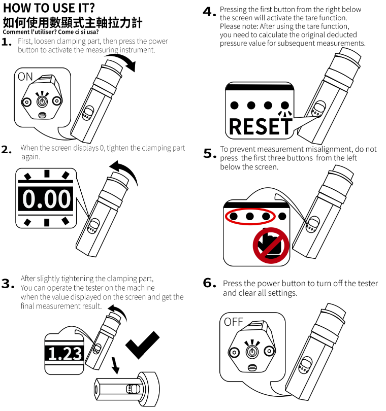
| 1.??????????????????????? ?????????? |  |
| 2.?????????????????? ???<?????>????? |  |
| 3.???????????3??reset?? |  |
| 4.?????????????????? ?????????????? |  |
| 5.?????????????????? |  |
| 6.???????????????????? ?????????????1 2 4? ?? |  |
| 7.??9V-USD???,TYPE-C??? ??????????? |  |
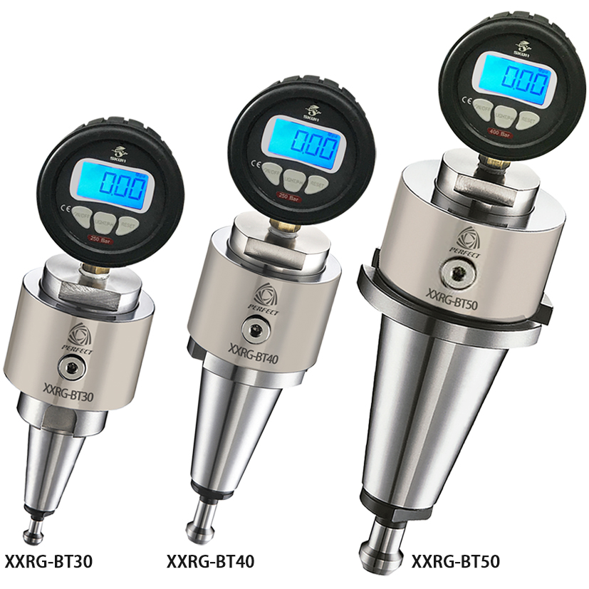
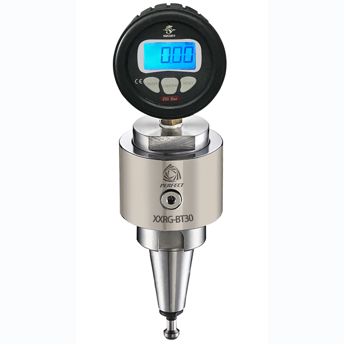
XXRG Digital Spindle Force Dynamometer
Characteristic
Model : XXRG
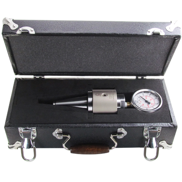
Spindle dynamometer (spindle tension meter) BT30, BT40, BT50? Features: Hydraulic mechanical structure, high stability
? Specifications Instructions:
1. Check if the tension gauge on the tension meter matches the four-claw gauge
Corresponding grid.
2. Tension meter and taper parts of the front spindle wipe clean,
Clamp tension meter can be.
3. Rally gauge pressure design: 1 kg / cm² = 10kg = 100 N
4. Taiwan's "SKON" production of digital display, LCD hydraulic gauge
Digital Spindle Force Dynamometer
Digital Spindle Force Dynamometer
|
Model |
Measuring range |
Package weight kg |
|
BT30-45° |
0~70bar tolerance ±0.5KG |
4.2KG |
|
BT30-60° |
||
|
BT30-90° |
||
|
JIS6339-30 |
||
|
ISO30 |
0~100bar tolerance ±1.0KG |
|
|
ISO30-R3 |
||
|
DIN30 |
||
|
SK30 |
|
Model |
Measuring range |
Package weight kg |
|
BT40-45° |
0~250bar tolerance ±20.KG |
4.3KG |
|
BT40-60° |
||
|
BT40-90° |
||
|
CAT40*45° |
||
|
CAT40*60° |
||
|
CAT40*90° |
||
|
ISO40-A |
||
|
ISO40-B |
||
|
MAZAK-40 |
||
|
JIS6339-40 |
||
|
DIN40 |
||
|
SK40 |
|
Model |
Measuring range |
Package weight kg |
|
BT50-45° |
0~400bar tolerance ±3.5KG |
6.7KG |
|
BT50-60° |
||
|
BT50-90° |
||
|
CAT50*45° |
||
|
CAT50*60° |
||
|
CAT50*90° |
||
|
ISO50 |
||
|
MAZAK-50 |
||
|
JIS6339-50 |
||
|
DIN50 |
||
|
SK50 |
1 bar=1.02kg/cm2
Digital Rally Meter Operating Instructions:
a: Pull force count explicit return to zero setting method
1. Turn the A rod to a loose turn so that it has no pressure.
2. Turn on (ON/OFF button) and press and hold (Light/P-H button)
3. Enter the mode setting, there will be a flashing number, press (REST
button) Set to “9”, press (Light/P-H) to enter standby time
Press (REST) to set to “5”, then press (Light/P-H) twice.
Will be automatically set to zero,
4. Press (ON/OFF) again to select the unit.
5. Tighten the A-pull rod again. At this time, the pressure value will
go up. Please stay at the most appropriate pre-pressure
value indicating that it should be between 5kg.
PS. To change the settings again,you have to wait for the shutdown
before you can make settings.
b: pull force counting explicit fueling method
1. First remove the plug from the B
2. Turn the "A" Pull studs to loose
3. Push the A rod inward again (to make the oil chamber oil
level retract)
4. Fill the R68 hydraulic oil from the B hole and lock the rear plug.
5."A" Pull studs can be pressurized to about 5KG.
c:Method of pull stud replacement
1. Use the adjustable wrench to clamp the seat of "D"
2. Turn the "A" Pull studs ("D" to hold )
3. Replace the new Pull studs "A" and lock it again.
4."A" Pull studs can be pressurized to about 5KG.
Screw thread 1/4PT 1 bar=1.02kg/cm2


1. boot display: After loading the battery, press and hold the power / unit key to display the current pressure value \
2. Pressure value to zero: When the pressure value is displayed, the zero button is pressed for three seconds, the pressure is zeroed.
3. Other proposed and set, see below.
Pressure gauge button function description:
A. Button Definition: There are three buttons on the pressure gauge panel
1. Power / Unit: The left button is - power / unit key
2. Backlight: The middle button is - Backlight
3. Zero button: The right button is - zero button
8. Parameter setting mode: At the same time, press and hold the backlight key, enter the parameter setting mode,
For details, see (3) Parameter setting mode.
C. Change the pressure unit: press the power / unit key click, that is, the current pressure unit change.
D. backlight switch: press the backlight key click, that is, turn on or off the backlight.
E. shows the maximum pressure value:
1. Press and hold the backlight key for three seconds, the LCD displays the maximum pressure value, and the "Max" pattern below the LCD flashes.
2. Press and hold the backlight key for 3 seconds, and return to normal working condition.
F. maximum pressure value zero:
In the state of displaying the maximum pressure value, press and hold the zero key for 3 seconds, the LCD will display "...." For 1 second, and the maximum pressure value will be zero.
G. Pressure value zero: Pressing the zero key for 3 seconds while the pressure value is displayed, the current pressure value is zero.
Parameter setting mode
A. The first item: zero mask setting
1. At the same time, press and hold the backlight key, enter the parameter setting mode.
2. Setting Mode The first item is to set the zero mask range, and the screen displays CUt.X.
3. Use the zero key to adjust the X number, X is 1-9.
B. second: shutdown time setting
1. Press the backlight key again, enter the setting mode The third is the shutdown time setting, the screen displays LCd.X.
2. Use the Zero key to adjust the number of X, X is 1-9.
C. Third: Turn off the backlight time setting
1. Press the backlight key again, enter the setting mode The third is to turn off the backlight time setting, the screen displays LEd.X.
2. Use the zero key to adjust the number of X, X is 1-9 D. The setting is completed - Save the setting:
1. Press the backlight key again, then the set value is memorized.
2. Then back to normal working status display

XXR-BT50 XXR-ISO Clamping Force Gauge
Characteristic
Model : XXR-BT50
Spindle Draw Bar force gauge? Product Features: Hydraulic mechanical structure, high stability
? Specifications Instructions:
1. Verify pull force gauge bolt specifications on with four claw specifications correspond.
2. Rally and the front spindle taper portion wipe clean,
Rally to clamp.
3. In response to the specifications of each knife, pull range as follows:
XXR-ISO Clamping Force Gauge
CAT50 Clamping Force Gauge
|
Model |
Meauring range |
Package weightkg |
|
BT50-45° |
0~350kg/? tolerance±5.3KG |
6.7KG |
|
BT50-60° |
||
|
BT50-90° |
||
|
CAT50*45° |
||
|
CAT50*60° |
||
|
CAT50*90° |
||
|
ISO50 |
||
|
MAZAK-50 |
||
|
JIS6339-50 |
||
|
DIN50 |
||
|
SK50 |


a: Check if the pre-pressure is in the available condition before using.
Inspection methods:
1. Pointer is not at zero, and there is left pre-pressure
2. Manually check the pressure gauge and if the body turns
if so, it means there is left pre-pressure. Otherwise,
if don't, that means there is no pre-pressure.
b: Method of reloading pre-presssure of dynamometer
1. Remove the screw B.
2. Loosen the pull stud A and loosen it again.
3. Push the pull stud A inwards (so that the oil level is reduced).
4. Fill R68 hydraulic fluid from hole B and then tighten the screw B.
5. Tighten the pull stud A. In the same time, Pointer C will be moving upward.
As the pull stud A is fully tightened, the proper pressure indication will be
between 10 to 30kg.
If it is over 30kg, loosen Screw B and let the indication be 10 to 30kg
c: Method of dynamometer dial indicator reading
1. The inner area of the dynamometer 10.00875 m?, so when the indication
times 10 is the correct pulling force.
2. An unit of dynamometer equals to 10kg
3. The digital dynamometer uses the Newton as 1 unit. (1kg = 9.8 N)
d: Method of pull stud replacement
1. fix the neck between the dial and the body
2. loosen the pull stub ( Do not move screw B)
3. Replace the new pull stub and tighten it up.
4. Check the pre-pressure if it is in the proper condition.
Conversion:
1 kg/cm² = 10kg = 100 N
E.g:25kg/?*10=250kg=25000??25K?

XXR-BT40 Spindle Force Dynamometer
Characteristic
Model : XXR-BT40
Model : XXR-BTSpindle Force Dynamometer
? Product Features: Hydraulic mechanical structure, high stability
? Specifications Instructions:
1. Verify pull force gauge bolt specifications on with four claw specifications correspond.
2. Rally and the front spindle taper portion wipe clean,
Rally to clamp.
3. In response to the specifications of each knife, pull range as follows:
Spindle Force Dynamometer
Spindle Force Dynamometer
|
Model |
Measuring range |
Weight |
|
BT40-45° |
0~160kg/? tolerance±2.4KG |
4.3KG |
|
BT40-60° |
||
|
BT40-90° |
||
|
CAT40*45° |
||
|
CAT40*60° |
||
|
CAT40*90° |
||
|
ISO40-A |
||
|
ISO40-B |
||
|
MAZAK-40 |
||
|
JIS6339-40 |
||
|
DIN40 |
||
|
SK40 |

a: Check if the pre-pressure is in the available condition before using.
Inspection methods:
1. Pointer is not at zero, and there is left pre-pressure
2. Manually check the pressure gauge and if the
body turns
if so, it means there is left pre-pressure.
Otherwise,
if don't, that means there is no
pre-pressure.
b: Method of reloading pre-presssure of dynamometer
1. Remove the screw B.
2. Loosen the pull stud A and loosen it again.
3. Push the pull stud A inwards (so that the oil level is reduced).
4. Fill R68 hydraulic fluid from hole B and then tighten the screw B.
5. Tighten the pull stud A. In the same time, Pointer C will be moving upward.
As the pull stud A is fully tightened, the proper pressure indication will be
between 10 to 30kg.
If it is over 30kg, loosen Screw B and let the indication be 10 to 30kg
c: Method of dynamometer dial indicator reading
1. The inner area of the dynamometer 10.00875 m?, so when the indication
times 10 is the correct pulling force.
2. An unit of dynamometer equals to 10kg
3. The digital dynamometer uses the Newton as 1 unit. (1kg = 9.8 N)
d: Method of pull stud replacement
1. Use the adjustable wrench to clamp the seat of "D"
2. Turn the A lever ("D" to hold )
3. Replace the new lever A and lock it again.
4. Check the preload again, if the preload is normal,
you can continue to use it.