Sign In


E-Catalog > รับจัดหาสินค้าอุตสาหกรรมและอะไหล่ทุกชนิด > AICHI TOKEI DENKI
Product Information :

- เครื่องจักร, อุปกรณ์เกี่ยวกับเครื่องจักร, เครื่องมือกล
- รับจัดหาสินค้าอุตสาหกรรมและอะไหล่ทุกชนิด
- สินค้า, ผลิตภัณฑ์
Product Detail :
- FOR GAS MEASUREMENT
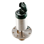
- SU
- Electromagnetic Water Meter
- SY
- Electromagnetic Water Meters
- SD15S
- Residential Water Meter
- TR-Ⅳ
- Portable Water Meter Test Kit
- E-Series
- Electronics Water Meter
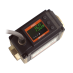
- CX
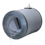
- Capacitive Electromagnetic Flowsensor
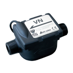
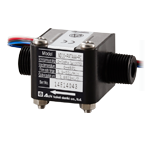
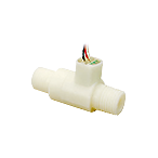
- VN
- Compact Electromagnetic Flow Sensor
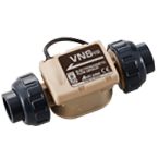
- VNS
- Compact Electromagnetic Flow Sensors

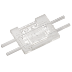
- OF-Z
- Microflow Sensor
- OF-WN/OF-WP
- Microstream Sensor
- ND
- Flow Sensor
- NW/NW-P
- Instantaneous Flow-rate/
Integrating Flow Volume Flowmeter
- NDV10
- Small-size Flowsensor
- DSV
- Disposable Electromagnetic Flowsensors
- TRA
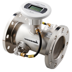
- Ultrasonic Flow Meter for Liquid
- AGV
- Electromagnetic Flow Meters
for Agricultural Applications
- FG
- Electromagnetic Flow Meter
for Non-Full Water

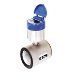
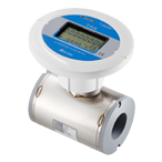
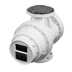
SUElectromagnetic Water Meter
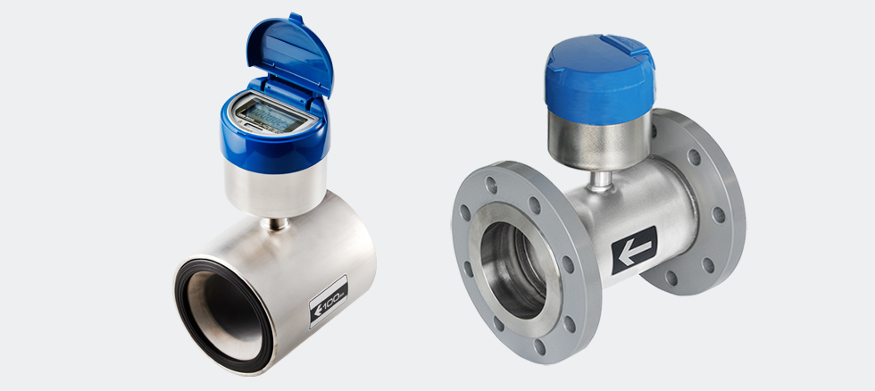
Electromagnetic Water Meter
Today, it is significant to capture the revenue while reducing the overall operating costs. Also, the water meters need to be more simple, accurate and reliable. Additionally, the compatibility with AMR/AMI and data-logging devices are required for water meters. SU is an ideal for a wide variety of bulk flow metering applications, such as network monitoring, leakage detection and commercial billing.
Solution

Feature

System Option

Display

CUSTOMER'S VOICES
Inova Control

Paraguay JICA

PDF Download
・SU50-200-KC (with SR-4) Drawing ・SU50-200-KC (with SR-4) Specifications
・SU50-200-KM Drawing ・SU50-200-KM Specifications
・SU50-200-KN Drawing ・SU50-200-KN Specifications
・SU250-350-KC (with SR-4) Drawing ・SU250-350-KC (with SR-4) Specifications
・SU250-350-KM Drawing ・SU250-350-KM Specifications
・SU250-350-KM-R Drawing ・SU250-350-KN Drawing
・SU250-350-KN SpecificationsDownload Catalog

・Specifications are subject to change without notice.
・Product Warranties
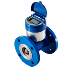
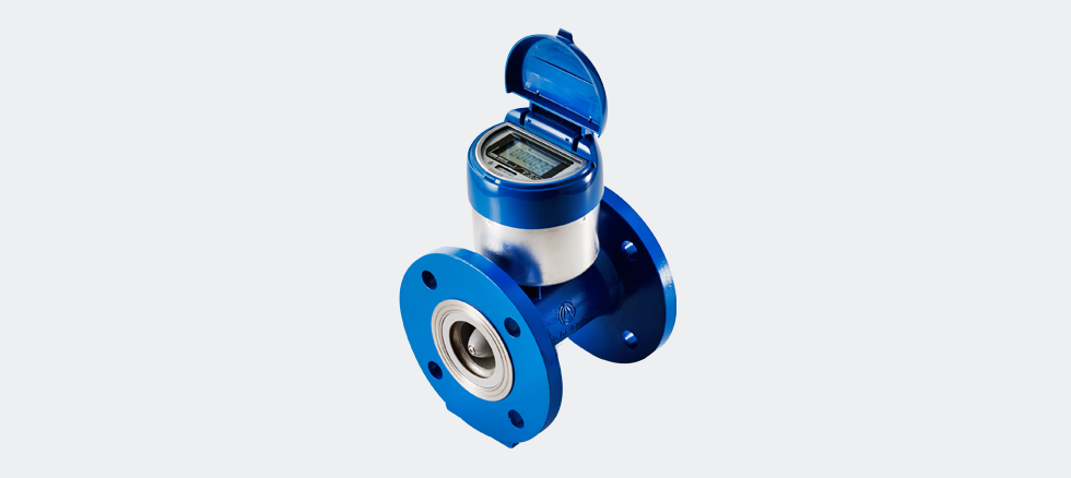
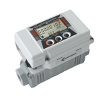
SYElectromagnetic Water Meters
Feature
| Measurement feature | Accurate measurement of small flowrate |
|---|---|
| Measurement range | 1:1000 |
| Measurable water | City water, plant water, agricultural water *1 |
| Meter connection method | Flange(JWWA standard) type |
| Body material | Cast stainless steel |
| Flow path | Cone structure |
Enhanced Durability! Lnnovative water meter for the new-era
As consumption of water has increased in the recent years, an advanced water meter has been desired for the use of long time and stable high accuracy measurement with trouble-free operation. Responding to these needs, Aichi has conducted proprietary research over and over and has succeeded in developing the world′s first electromagnetic water meter “SU Series” and “SY Series” that provides 8 years of non-stop service with built-in battery. These water meters for the new-era are suitable for water control with innovative enhanced durability that expands the world of measurement.
Outstanding features that expand the world of measurement
Outstanding durability with no moving parts
Since there are no rotating or sliding parts such as vane wheel or indication gears, troubles caused by wear of moving parts and intrusion of foreign substances are eliminated. Therefore, stable measuring accuracy can be maintained over a long period of time.
High accuracy measurement whether large continuous or small flowrates
The SU Series has almost no head pressure loss at maximum flowrate measurement, it is suitable for measuring flowrates of large continuous water supply and distribution. The SY Series is capable of measuring small flowrates with high accuracy owing to its special structure.
Wider measurement range
The measurement range is as wide as 1:200 for the SU Series, and 1:1000 for the SY Series. High-accurate measurement from very small (min. accurate flowrate) to large (max. flowrate) flowrates is possible.
8 years of continuous operation with a built-in battery
The power consumption has been reduced to 1/1000 (according to Aichi’s comparison data) from the conventional general electromagnetic flowmeter, and with a built-in lithium battery applied, 8 years of continuous measurement is realized. Consequently, there is no need of maintenance during this period.
Constant display on easy-to-read LCD
Bright and large LCD have been incorporated for the digital display of integrated flow and instantaneous flowrate values of all times. By utilizing such instantaneous flowrate value, flowrate adjustment of water supply and distribution can be easily performed.
Free installation position allows installation anywhere
Having no mechanical moving parts, the meter can be installed on a horizontal, vertical or inclined position, allowing installation anywhere with very little restriction for its location.
All stainless steel body with outstanding durability
Both the compact design wafer type (SU)* and easy-to-install flange type (SY) are made of all stainless steel body having the feature of long life. *The SU with 250, 300 and 350mm nominal diameters are flange types.
Flexible corresponding to various systems of specific use
Since these meters are equipped with electronic statement signal output function, installation of transmitter for specific use will enable flexible corresponding to various systems such as remote meter reading, automatic meter reading, as well as monitoring and controlling.
Overview
| Item | |||||
|---|---|---|---|---|---|
| Nominal diameter | 50 | 75 | 100 | 150 | |
| Flow-rate range | Max. flow-rate (2qp)(m3/h) | 40 | 90 | 160 | 300 |
| Standard flow-rate (qp)(m3/h) | 20 | 45 | 80 | 150 | |
| Transitional flow-rate (qt)(m3/h) | 4 | 9 | 16 | 30 | |
| Min. flow-rate (qmin)(m3/h) | 0.6 | 1.35 | 2.4 | 4.5 | |
| Min. accurate flow-rate (qc)(m3/h) | 0.04 | 0.09 | 0.16 | 0.3 | |
| Measurement starting flow-rate (qs)(m3/h) | 0.01 | 0.0225 | 0.04 | 0.075 | |
| The meter does not measure a flowrate less than the measurement starting flowrate (qs). The qs to qmin flowrate range is not within the calibration tolerance. | |||||
| Max. limit flow-rate (qL)(m3/h) | 60 | 120 | 200 | 400 | |
| The 2qp to qL flowrate region is not within the calibration tolerance. | |||||
| Pressure drop at max. flow-rate (MPa) | 0.041 | 0.039 | 0.035 | 0.032 | |
| Working pressure (MPa) | 0.75 (Approx. 7.5kgf/cm2) | ||||
| Display | Integrating flow (m3) | 999999.9999 | 9999999.999 | ||
| Instantaneous flow-rate (m3/h) | 99.99 | 999.9 | |||
| Meter weight (kg)10121625 | 10 | 12 | 16 | 25 | |
| Item | |||
|---|---|---|---|
| Display | No-water warning mark | ||
| Low-battery alarm mark | |||
| Measurement stop alarm mark | |||
| Measured fluid | Suitable working temperature (°C) | 0 to +30 | |
| Fluid conductivity rate (μs/cm) | 50 or more | ||
| Power supply and battery life | Lithium battery (Nominal 3.6V), battery life approx. 8 years (At average environmental temperature of 20°C) | ||
| Environmental temperature range (°C) | -10 to +55 (The battery life is shortened at higher temperature.) | ||
| Waterproof structure | JIS C0920 (Underwater use), continuous use at 1m water depth is possible | ||
| Piping method | Flange (JWWA standard) type | ||
| Meter installation position | Free (Horizontal, vertical and inclined installation are possible.) | ||
| External output | SY-FN type | No external output functions (Only field display) | |
| SY-FC type | Electronic statement signal for exclusive independent receiver (SR-4 type) | Transmitter: MX35 type | |
| SY-FM type | Open drain unit pulse signal | Transmitter: MX39 type | |
| SY-FL type | 8-bit electronic statement signal (The signal widely diffused in Japan for water and gas meters), open drain unit pulse signal | Transmitter: MX38 type | |
Accuracy

Head Loss

Dimensions

Transmitter specifications MX Series

MX35 type
| Signal | Electronic statement signals for exclusive independent receiver (SR-2 type) |
|---|---|
| Number of wires | 2 |
| Transmitting distance | 50m with standard cable |
| Life | Approx. 10 years |
MX39 type
| Signal | Open drain unit pulse |
|---|---|
| Pulse ON time | 100±10ms |
| Pulse unit | 100L/P or 1m3/P (10m3/p·special specification) |
| Number of wires | 2 |
| Transmitting distance | 200m with standard cable |
| Life | Approx. 10 years |
MX38 type
| Signal | 1) Ver. 2.6A Only 8-bit electronic statement 2) Ver. 2.6A 8-bit electronic statement and open drain unit pulse |
|---|---|
| Number of wires | 2 wires for 1), 4 wires for 2) |
| Transmitting distance | 200m with standard cable (When connected with independent type receiver QA8D-1R) |
| Life | Approx. 8 years (Differs according to number of readings) |
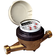
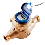
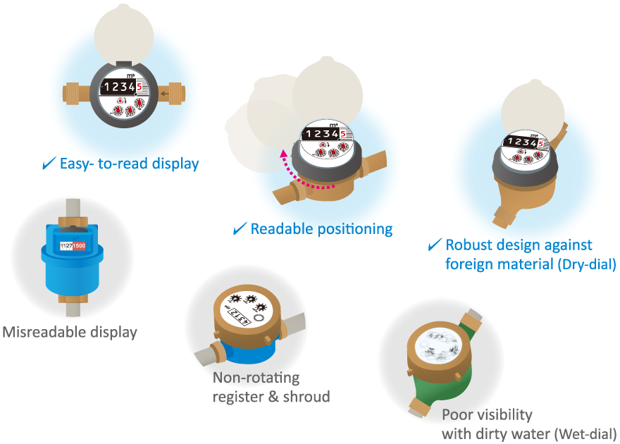
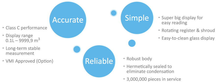
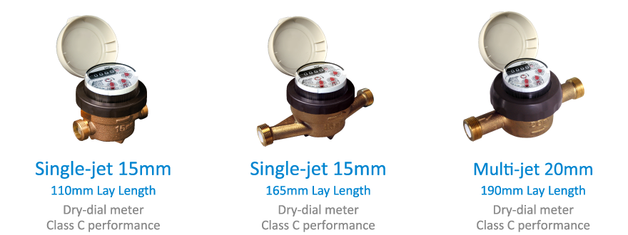
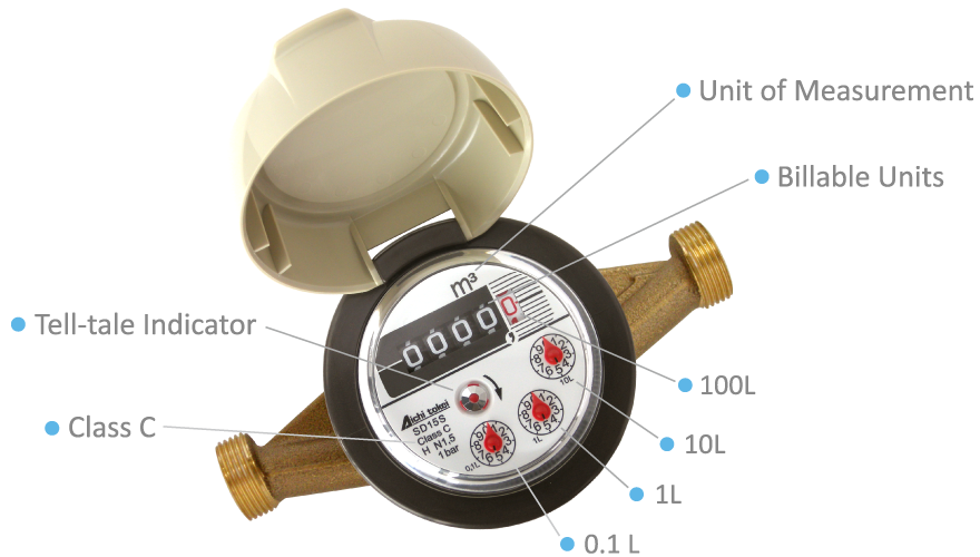
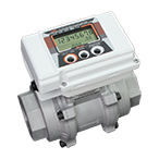
SD15SResidential Water Meter
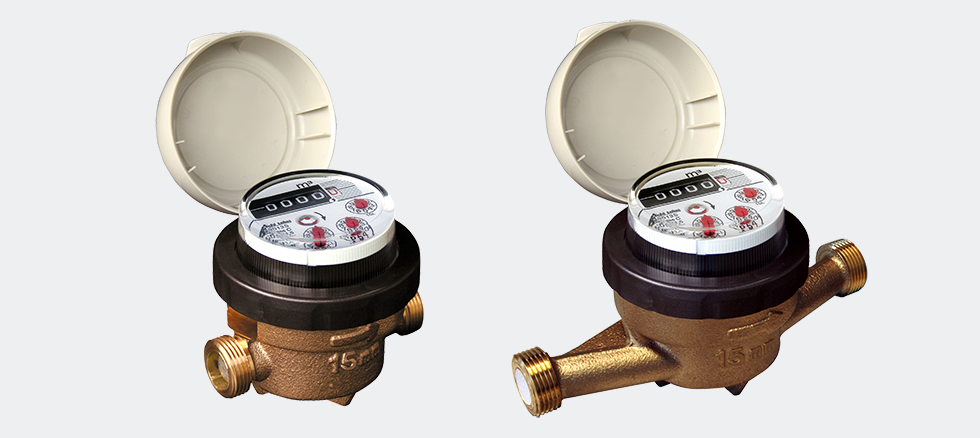
Residential Water Meter
Many water utilities in the world challenge in improving the water management such as non-revenue water reduction, efficient use of water resources, safe & stable drinking water distribution and so on. Collecting the accurate meter data is essential for this improvement. The Aichi Tokei Denki SD Single-jet Water Meter is suitable for this application because it is not only accurate but also cost-effective & robust.
Solution
Feature
System Option
Display
Download Catalog
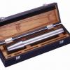
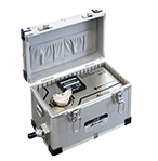
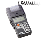
TR-ⅣPortable Water Meter Test Kit
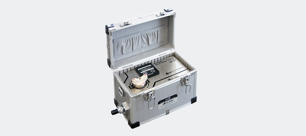
Portable Water Meter Test Kit that combines portability, easy-to-handle and reliability
Today, it is significant to capture the revenue while reducing the overall operating costs. Also, the water meters need to be more simple, accurate and reliable. TR-Ⅳ is an ideal for the field use of performing comparison testing on installed water meters for accuracy and performance. TR-Ⅳ is portable water meter test kit for 15mm, 20mm and 25mm. It is compact, light weight and accurate which can provide you the data for water meter replacement program for the improvement of non-revenue management.
Solution
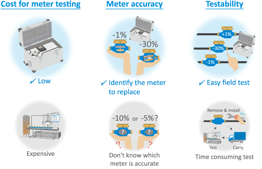
Feature

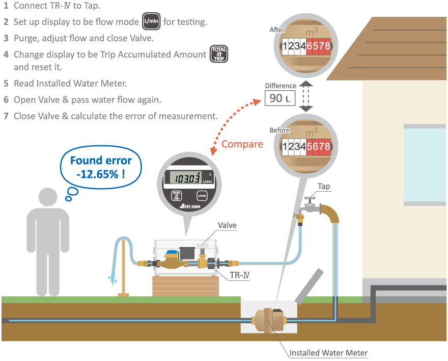
Test Image
Download Catalog
- FOR GAS MEASUREMENT
- TRX/TRZ
- Ultrasonic Flow Meter
For Compressed Air and Nitrogen

- TRX
- Ultrasonic Flow Meters
For Compressed Air and Nitrogen (Diameters 40A, 50A, 65A, and 80A)
- TRZ
- Ultrasonic Flow Meters
For Compressed Air and Nitrogen (Diameters 100A, 150A and 200A)
- AS-W
- Ultrasonic Flow Meter
For Fuel Gas
- AS-WE
- Ultrasonic Flow Meter
For Fuel Gas (CE-marked version)
- TBX/TBZ
- Turbine Gas Meters
for Flow Management
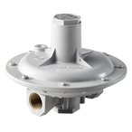
- Governor
- Pressure-reducing valve series
- Roots
- Gas Meter R Series
- UX
- Ultrasonic Flow Meter
For Fuel Gas Control
- UX/UZ
- Ultrasonic Flow Meter
For Fuel Gas Control
- NB
- Intelligent Gas Meter
- HX
- Taking up challenges in new measurement
- MP-401
- Digital Manometer
for Town Gas and LP Gas
GovernorPressure-reducing valve series
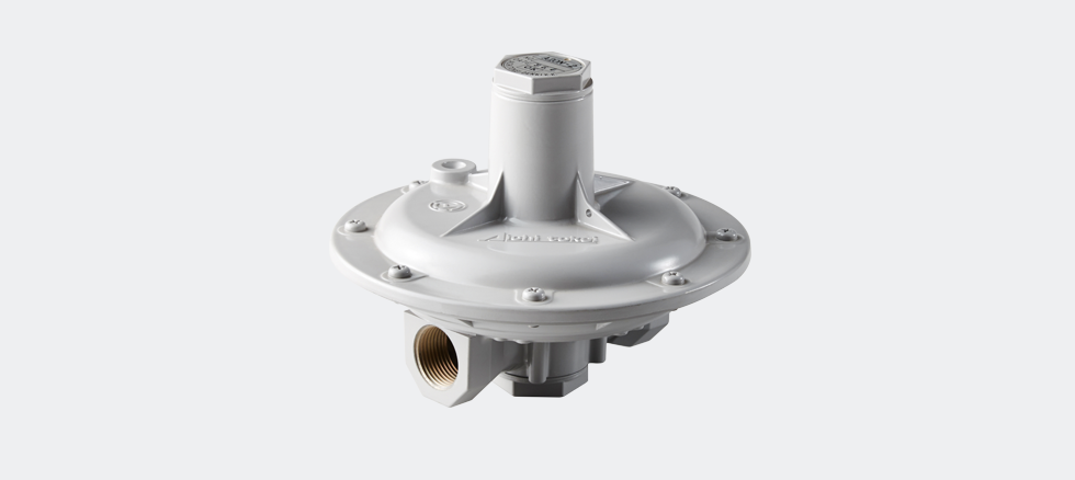
Pressure-reducing valve series


The governors introduced here are the standard products of Aichi.
The following types of governors are also available. Please contact us for the product details.
・Governor for high temperatures
・Governor with a fine-tuning handle
・Governor for gases containing sulfide
・Other special governors
TRXUltrasonic Flow Meters
For Compressed Air and Nitrogen (Diameters 40A, 50A, 65A, and 80A)
Features
A cost effective ultrasonic flow meter specialized for measuring air and nitrogen is now available!
It has realized a wide range of measuring ability and ZERO pressure loss using the characteristics of ultrasonic waves. It is also well-equipped to handle dust and mist and has excellent durability compared with conventional flow meters that use other measuring principles because it does not have moving parts.
The meter can be selected from two types of power sources: built-in batteries that can run 10 years without needing power construction, or an external power supply (24 VDC).
・To understand and visualize the usage of compressed air as a measure of saving electric power.. ・To understand the amount of nitrogen refined and used in a factory. (Can be applied to a degreasing treatment.)
Specifications
| Model | External power specifications | TRX40D-C/5P | TRX50D-C/5P | TRX65D-C/5P | TRX80D-C/5P |
|---|---|---|---|---|---|
| Built-in battery specifications | TRX40B-C/5P | TRX50B-C/5P | TRX65B-C/5P | TRX80B-C/5P | |
| Diameter (Nominal diameter) | 40A | 50A | 65A | 80A | |
| Power source | External power specifications | 24 VDC ± 10%; Power consumption: 1.1 W or less | |||
| Built-in battery specifications | Lithium battery with a battery life of about 10 years (under an environmental temperature of 20°C) | ||||
| Measurable fluids | Air (mainly the air in a factory) or nitrogen * Please select when ordering. | ||||
| Fluid temperature and humidity | – 10 to 60°C and 90% RH or less | ||||
| Operating pressure | Less than 0 to 1 MPa (Gauge pressure) | ||||
| Flow rate range (Actual flow) | ±1.3~80m3/h | ±2.5~150m3/h | ±4~240m3/h | ±5~300m3/h | |
| Flow measurement accuracy | ±2%RS | ±8~80m3/h | ±15~150m3/h | ±24~240m3/h | ±30~300m3/h |
| ±5%RS | ±1.3~8m3/h | ±2.5~15m3/h | ±4~24m3/h | ±5~30m3/h | |
| Low flow rate cut-off | ±0.2m3/h | ±0.4m3/h | ±0.5m3/h | ±0.8m3/h | |
| Normal conversion accuracy | ± 2.5% (at 500 kPa and 25°C) | ||||
| Display (Switched by buttons) | Model | LCD 7 segments (with unit and alarm displays) | |||
| Main display *2 | [Forward flow display mode] Accumulated flow rate: 00000000.0 (Nm3/h) in 9 digits Trip accumulated flow rate: 0000000.0 (Nm3/h) in 8 digits Instantaneous flow rate: 00000.00 (NL/min) in 7 digits | ||||
| [Forward and reverse flow display mode] Forward accumulated flow rate: 00000000.0 (Nm3/h) in 9 digits Reverse accumulated flow rate: -0000000.0 (Nm3/h) in 8 digits Instantaneous flow rate: 00000.00 (NL/min) in 7 digits | |||||
| Sub display | Instantaneous flow rate: 000.00 (Nm 3/h, less than 200 Nm3/h) in 5 digits 0000.0 (Nm 3/h, 200 Nm3/h or more and less than 2000 Nm3/h) in 4 and 1/2 digits 00000 (Nm 3/h, 2000 Nm3/h or more) in 5 digits [200 A × 10] | ||||
| Pressure: 0000.0 kPa in 5 digits Temperature: 00.0°C in 3 digits | |||||
| Output | Current output | 4 to 20 mA (± 0.5% FS); Load resistance: 400 Ω or less; Upper output current: 22 mA Select output from instantaneous flow rate, pressure, and temperature by pressing a button. A separate power supply (24 VDC ± 10%) is necessary if you use the meter of the built-in battery specifications. *1 | |||
| Output range (4 to 20 mA): Instantaneous flow rate 0 to ☐☐☐☐ Nm3/h (Forward flow display mode) – ☐☐☐☐ to ☐☐☐☐ Nm3/h (Forward and reverse flow display mode) ☐☐☐☐ are the values set by the button. | |||||
| Pressure: 0 to 1000 kPa Temperature: -10 to 60°C | |||||
| Contact output | Two Open-drain output systems Maximum load: 24 VDC, 10 mA Maximum frequency: 10 Hz Duty: 35% to 65% | ||||
| Output 1: Unit pulse (Forward flow) Output 2: Unit pulse (Reverse flow) Flow rate upper and lower limits alarm Selection of telegram output | |||||
| Pulse output units: 100 NL/P or 1000 NL/P | |||||
| Connection method | Wafers (Fixed by JIS 10 K flanges) | ||||
| Mounting position | Horizontal (LCD display to be placed upward), or vertical mounting | ||||
| The materials exposed to gases | Aluminum alloy, PPS, fluorosilicone rubber, etc. | ||||
| Mass | External power specifications | 1.0kg | 1.2kg | 1.4kg | 1.7kg |
| Built-in battery specifications | 1.1kg | 1.3kg | 1.6kg | 1.8kg | |
| Installation location | Indoor and outdoor (The safety class IP64 qualified) | ||||
| Storage temperature | -20 to 70°C; No condensing | ||||
| Regulatory compliance | CE marking compliant (EN 61000- 6-2:2005 and EN 61000- 6-4: 2007) | ||||
*1: In the actual flow measurement setting, the digits of the accumulated flow rate display, instantaneous flow rate display and pulse output vary. *2: When displaying the instantaneous flow (NL /min), the main display (accumulated flow rate), sub-display (instantaneous flow rate [Nm3/h]), pressure (kPa) and temperature (°C) will not be displayed. * Piping conditions: 20D or higher in upstream and 5D or higher in downstream for the 25A/32A models. (When using in the forward and reverse display mode, 20D or higher on both sides.) 10D or higher in upstream and 5D or higher in downstream for the 40A or larger models. (When using in the forward and reverse display mode, 10D or higher on both sides.) For more information, please contact our sales and branch offices.
Conversion chart between actual and normal flow rates
| Conversion conditions | 40A | 50A | 65A | 80A | |||||
|---|---|---|---|---|---|---|---|---|---|
| Temperature (°C) | Gauge pressure (MPa) | Minimum | Maximum | Minimum | Maximum | Minimum | Maximum | Minimum | Maximum |
| Actual flow rate (m3/h) | 1.3 | 80 | 2.5 | 150 | 4 | 240 | 5 | 300 | |
| 20 | 0.7(Nm3/h) | 9.6 | 590 | 18 | 1100 | 30 | 1770 | 37 | 2210 |
| 30 | 0.5(Nm3/h) | 7.0 | 430 | 13 | 800 | 21 | 1280 | 27 | 1600 |
| 0.7(Nm3/h) | 9.3 | 570 | 18 | 1070 | 29 | 1710 | 36 | 2140 | |

Dimensions
(Unit: mm)
| Model | W | D | H | Mass |
|---|---|---|---|---|
| TRX40 | 76 | 81 | 163 | 1.1 kg (1. Built-in lithium battery model) 1.0 kg (2. External power supply model) |
| TRX50 | 90 | 96 | 176 | 1.3 kg (1. Built-in lithium battery model) 1.2 kg (2. External power supply model) |
| TRX65 | 108 | 117 | 197 | 1.5 kg (1. Built-in lithium battery model) 1.4 kg (2. External power supply model) |
| TRX80 | 117 | 126 | 220 | 1.8 kg (1. Built-in lithium battery model) 1.7 kg (2. External power supply model) |

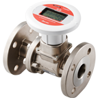
AS-WUltrasonic Flow Meter
For Fuel Gas
AS-W Series
Since AS-W flow meter covers wider range from small to large flow rate, it contributes to cost saving and convenient facility management. At the same time, it saves the cost of redundant governor and piping.
・ Non-moving parts results in not degrading meter performance. It eventually makes needless to repair the parts and refuel the lubricant oil.
・ Because of the pressure loss being closely “0”, it can get rid of the pressure shortage risk.
・ Because of lightweight and compact feature, it enables easy installation and needs less space.
Product Specifications
| Model | AS-W-25 | AS-W-32 | AS-W-40 | AS-W-50 | AS-W-80 | AS-W-100 | AS-W-150 | AS-W-200 | |||
|---|---|---|---|---|---|---|---|---|---|---|---|
| Nominal diameter | 25A | 32A | 40A | 50A | 80A | 100A | 150A | 200A | |||
| Power supply | Built-in lithium batteries | ||||||||||
| Years of duration | 6 years (At surrounding temperature of 20℃) (Exclunding 1 year of storage period) |
||||||||||
| Measurable fluids | Natural gas and air | ||||||||||
| Working pressure (Absolute pressure) |
0∼0.5MPa(AS-WW-□-500B[A/G]/3) 0∼0.2MPa(AS-WW-□-200B[A/G]/3) 0∼0.5MPa(AS-WW-□-0B[A/G]/3) |
0∼1.0MPa(AS-WW-□-1000B[A/G]/3) 0∼0.5MPa(AS-WW-□-500B[A/G]/3) 0∼0.2MPa(AS-WW-□-200B[A/G]/3) 0∼1.0MPa(AS-WW-□-0B[A/G]/3) |
|||||||||
| Accuracy | Flowrate measurement accuracy *1 | ±5%RS (m³/h) | Actual flow rate (m³/h) | ±0.7 ∼ 7 | ±1.3 ∼ 13 | ±1.6 ∼ 16 | ±3 ∼ 30 | ±6 ∼ 60 | ±10 ∼ 100 | ±24 ∼ 240 | ±40 ∼ 400 |
| ±2%RS (m³/h) | Actual flow rate (m³/h) | ±7 ∼ 35 | ±16 ∼ 65 | ±16 ∼ 80 | ±30 ∼ 150 | ±60 ∼ 300 | ±100 ∼ 500 | ±240 ∼ 1200 | ±400 ∼ 2000 | ||
| Low flow cut-off (Initial flow rate) *2 | Flow rate (m/s) | 0.05 m/s or less | |||||||||
| Actual flow rate (m³/h) | ±0.1 | ±0.2 | ±0.2 | ±0.4 | ±0.8 | ±1.5 | ±3.2 | ±5.7 | |||
| Fluid temperature and humidity | -20 to +60℃, 90% RH or less | ||||||||||
| Pressure loss | Zero (Equivalent to straight tube part) | ||||||||||
| Display | Accumulated flow volume | Accumulated flow volume: 00000000.0 (9 digits/m³ or Nm³) | Accumulated flow volume: 0000000000 (10 digits/m³ or Nm³) | ||||||||
| Instantaneous flow rate *3 | (1) Maximum indication value: ±19999Nm³/h (converted flow rate) (2) Maximum indication value: ±19999Nm³/h (actual flow rate) (Two decimal places for a value less than 200, one decimal place for a value from 200 to less than 2000, integer only for a value of 2000 or more) |
||||||||||
| Temperature *3 | 00.0℃ (3-digits) | ||||||||||
| Pressure *3 | 0000.0kPa (5-digits) | ||||||||||
| Output | Contact output | Open drain output: Unit pulse (forward flow) Pulse unit: 100,1000,10000 (L/P or NL/P) |
|||||||||
| Telegram output | RS485 Modbus/RTU | ||||||||||
| Connection method | ISO7-1 Taper screw connection(JISB 0203, BS21, GB/T7306, 2-2000) equivalent | ISO7005-1 (GB/T9119-2002 PN1.6MPa Flange) equivalent *4 | |||||||||
| Installation position | Horizontal and vertical | ||||||||||
| Installation location | Indoor and outdoor (protection level IP 64 or equivalent) | ||||||||||
| Case material | Aluminum alloy | Stainless alloy | |||||||||
| The materials exposed to gases | Aluminum alloy and engineering plastic | Stainless alloy and engineering plastic | |||||||||
| Mass | 1.8kg | 1.7kg | 7.6kg | 9.6kg | 13.3kg | 13.2kg | 20.4kg | 35.4kg | |||
*1. The flow rate measurement range is ±5% RS: Inclusive before “∼” and not inclusive after “∼” and ±2% RS: Inclusive for both before and after “∼”.
*2. When the flow rate is less than 0.25% of the maximum flow rate, the instantaneous flow rate is indicated as 0 m³/h. For the normal conversion type, the low flow cut off value is the normal conversion flow rate corresponding to 0.05 m/s.
*3. Automatically switched in every 4 seconds.
*4. This flowmeter guarantees the flow measurement accuracy with the pipes listed in the table below.
(If you use pipes with the different pipe standard and size not listed in the table, the flowmeter may not satisfy the flow measurement accuracy. Consult us in advance if it is considered to use different pipes out of this range.)
| Pipe standard | G3459 JIS 10K | EN10208 | ||||||
|---|---|---|---|---|---|---|---|---|
| Nominal diameter(mm) | 25 | 32 | 40 | 50 | 80 | 100 | 150 | 200 |
| External diameter(mm) | 34 | 42.7 | 48.3 | 57 | 88.9 | 108 | 159 | 219.1 |
| Thickness(mm) | 2.8 | 2.8 | 4 | 3.5 | 4.5 | 4 | 4.5 | 10 |
AS-WEUltrasonic Flow Meter
For Fuel Gas (CE-marked version)
AS-WE Series
Since AS-WE flow meter covers wider range from small to large flow rate, it contributes to cost saving and convenient facility management. At the same time, it saves the cost of redundant governor and piping.
・ Non-moving parts results in not degrading meter performance. It eventually makes needless to repair the parts and refuel the lubricant oil.
・ Because of the pressure loss being closely “0”, it can get rid of the pressure shortage risk.
・ Because of lightweight and compact feature, it enables easy installation and needs less space.
Product Specifications
| Model | AS-WE-40 | AS-WE-50 | AS-WE-80 | AS-WE-100 | AS-WE-150 | AS-WE-200 | |||
|---|---|---|---|---|---|---|---|---|---|
| Nominal diameter | 40A | 50A | 80A | 100A | 150A | 200A | |||
| Power supply | Built-in lithium batteries | ||||||||
| Years of duration | 6 years (At surrounding temperature of 20℃) (Exclunding 1 year of storage period) |
||||||||
| Measurable fluids | Natural gas and air | ||||||||
| Working pressure | 0.05Mpa (Gauge pressure) | ||||||||
| Pressure sensor | Without pressure compensation : AS-WE-□-0B/3 With pressure compensation : AS-WE-□-200BG/3 (gauge pressure sensor) : AS-WE-□-200BA/3 (absolute pressure sensor) |
||||||||
| Accuracy | Flowrate measurement accuracy *1 | ±5%RS (m³/h) | Actual flow rate (m³/h) | ±1.6 ∼ 16 | ±3 ∼ 30 | ±6 ∼ 60 | ±10 ∼ 100 | ±24 ∼ 240 | ±40 ∼ 400 |
| ±2%RS (m³/h) | Actual flow rate (m³/h) | ±16 ∼ 80 | ±30 ∼ 150 | ±60 ∼ 300 | ±100 ∼ 500 | ±240 ∼ 1200 | ±400 ∼ 2000 | ||
| Low flow cut-off (Initial flow rate) *2 | Flow rate (m/s) | 0.05 m/s or less | |||||||
| Actual flow rate (m³/h) | ±0.2 | ±0.4 | ±0.8 | ±1.5 | ±3.2 | ±5.7 | |||
| Fluid temperature and humidity | -20 to +60℃, 90% RH or less | ||||||||
| Pressure loss | Zero (Equivalent to straight tube part) | ||||||||
| Display | Accumulated flow volume | Accumulated flow volume: 00000000.0 (9 digits/m³ or Nm³) |
Accumulated flow volume: 0000000000 (10 digits/m³ or Nm³) |
||||||
| Instantaneous flow rate *3 | (1) Maximum indication value: ±19999Nm³/h (converted flow rate) (2) Maximum indication value: ±19999Nm³/h (actual flow rate) (Two decimal places for a value less than 200, one decimal place for a value from 200 to less than 2000, integer only for a value of 2000 or more) |
||||||||
| Temperature *3 | 00.0℃ (3-digits) | ||||||||
| Pressure *3 | 0000.0kPa (5-digits) | ||||||||
| Output | Contact output | Open drain output: Unit pulse (forward flow) Pulse unit: 100,1000,10000 (L/P or NL/P) |
|||||||
| Telegram output | RS485 Modbus/RTU | ||||||||
| Connection method | ISO7005-1 (GB/T9119-2002 PN1.6MPa Flange) equivalent *4 | ||||||||
| Installation position | Horizontal and vertical | ||||||||
| Installation location | Indoor and outdoor (protection level IP 64 or equivalent) | ||||||||
| Case material | Stainless alloy | ||||||||
| The materials exposed to gases | Stainless alloy and engineering plastic | ||||||||
| Mass | 7.6kg | 9.6kg | 13.3kg | 13.2kg | 20.4kg | 35.4kg | |||
*1. The flow rate measurement range is ±5% RS: Inclusive before “∼” and not inclusive after “∼” and ±2% RS: Inclusive for both before and after “∼”.
*2. When the flow rate is less than 0.25% of the maximum flow rate, the instantaneous flow rate is indicated as 0 m³/h. For the normal conversion type, the low flow cut off value is the normal conversion flow rate corresponding to 0.05 m/s.
*3. Automatically switched in every 4 seconds.
*4. This flowmeter guarantees the flow measurement accuracy with the pipes listed in the table below.
(If you use pipes with the different pipe standard and size not listed in the table, the flowmeter may not satisfy the flow measurement accuracy. Consult us in advance if it is considered to use different pipes out of this range.)
| Pipe standard | EN10208 | |||||
|---|---|---|---|---|---|---|
| Nominal diameter(mm) | 40 | 50 | 80 | 100 | 150 | 200 |
| External diameter(mm) | 48.3 | 57 | 88.9 | 108 | 159 | 219.1 |
| Thickness(mm) | 4 | 3.5 | 4.5 | 4 | 4.5 | 10 |
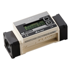
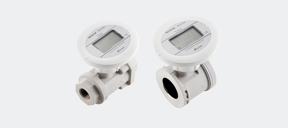
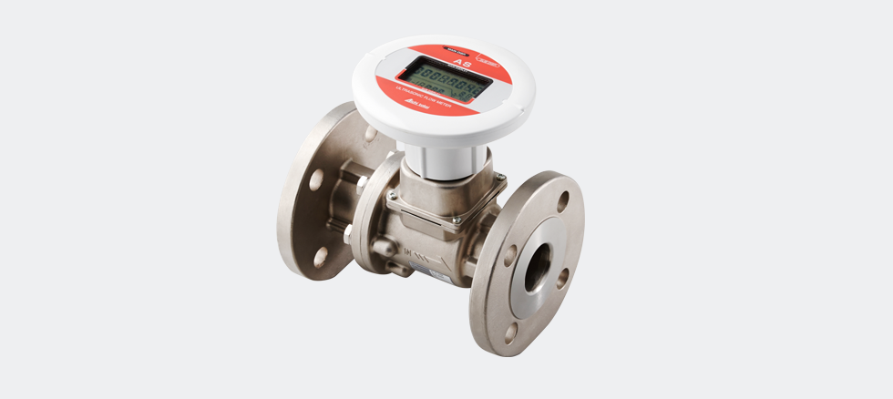
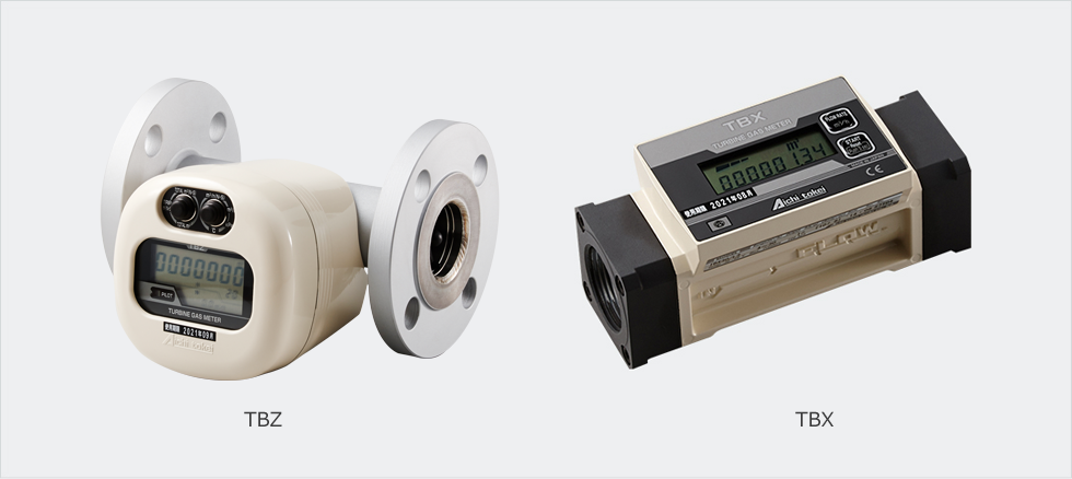
TBX/TBZTurbine Gas Meters
for Flow Management
Features
Turbine meters in the TBZ and TBX series were developed for controlling the gas consumption of each piece of equipment such as compact boilers and various industrial furnaces.
The products realize a smart design with a lightweight and compact body and support a wide range of measurement including maximum working pressure and maximum measuring flow rate.
Furthermore, the built-in 2-system pulse transmitters enable you to establish a remote meter reading system and an energy control system.
The TBZ series even corrects temperature and pressure to allow you to read gas consumption in the standard conversion condition.
The external power supply model TBX-D has been newly added to the lineup of the TBX series. You can choose the model that would best suit your applications for better usability.
Note) TBX30, TBX100, and TBX100F are CE compliant. (Collaborative development product with Tokyo Gas Co., Ltd.)
・The maximum working pressure covers low, medium and high pressures. ・Free installation positions..  ・Equipped with two systems of pulse transmitter. ・Supports a variety of gases and a wider range of applications. ・LCD display that gives you more information. ・Corrects temperature and pressure. (TBZ series). ・Non-stop operation for seven years. (For the battery specifications)
Application examples
・Manage and control gas flows of burning equipment such as burners, boilers and furnaces. ・Manage and control flows of hot and chilled water generators in compact to medium sizes. ・Manage and control flows of gas refrigerators. ・Manage and control gas flows as a part of plant instrumentation. ・For various experimental devices relating to gas flows.
System drawing

Specifications
The model with the correcting function (TBZ series)
| Basic model | TBZ60 | TBZ150 | TBZ300 | |||||||
|---|---|---|---|---|---|---|---|---|---|---|
| Model name | Flow rate correcting model (with the functions of temperature and pressure correction) | – | TBZ 60-3.5 | TBZ 60-9.9 | – | TBZ 150-3.5 | TBZ 150-9.9 | – | TBZ 300-3.5 | TBZ 300-9.9 |
| Actual flow rate model (without the functions of temperature and pressure) | TBZ 60-0 | – | – | TBZ 150-0 | – | – | TBZ 300-0 | – | – | |
| Operating flow rate range *1 | 6~60m3/h | 12.5~150m3/h | 30~300m3/h | |||||||
| Maximum operating pressure | 980kPa | 350kPa | 980kPa | 980kPa | 350kPa | 980kPa | 980kPa | 350kPa | 980kPa | |
| Accuracy | Flow rate measuring parts | ±1%FS and ±3%RS | ||||||||
| Operator parts and temperature and pressure correction parts | – | ±2% RSmax | ±3% RSmax | – | ±2% RSmax | ±3% RSmax | – | ±2% RSmax | ±3% RSmax | |
| Display | Corrected gross accumulated flow rate (Only for the corrected flow rate model) | Large LCD in 9 digits with minimum reading of 10 L | Large LCD in 9 digits with minimum reading of 100 L | |||||||
| Trip flow rate *2 | Large LCD in 8 digits with minimum reading of 10 L | Large LCD in 8 digits with minimum reading of 100 L | ||||||||
| Unadjusted gross accumulated flow rate *3 | Large LCD in 9 digits with minimum reading of 10 L | Large LCD in 9 digits with minimum reading of 100 L | ||||||||
| Corrected instantaneous flow rate (Only for the flow rate correction model) | LCD in 4 digits with minimum reading of 0.1 m3/h | LCD in 4 digits with minimum reading of 1 m3/h | ||||||||
| Unadjusted instantaneous flow rate | LCD in 4 digits with minimum reading of 0.1 m3/h | LCD in 4 digits with minimum reading of 1 m3/h | ||||||||
| Temperature (Only for the models with temperature and pressure correction) | LCD in 3 digits with minimum reading of 0.1 m3/h | |||||||||
| Pressure (Only for the corrected flow rate model) | LCD in 3 digits with minimum reading of 0.1 m3/h | |||||||||
| Diameters of connected parts | JIS 10K 40A flange | JIS 10K 50A flange | JIS 10K 80A flange | |||||||
| Operating temperature range | -10℃~+60℃ | |||||||||
| Measurable gases *4 | Town gas, LPG, nitrogen, etc. | |||||||||
| Mounting position | Horizontal and Vertical (Display supports both directions.) | |||||||||
| Installation location | Indoor and outdoor * 5 | |||||||||
| Case structure | Drip-proof structure, IPX 2 equivalent (JIS-CO920) | |||||||||
| Power source | Built-in lithium battery | |||||||||
| Output signal | Two systems of open collectors (corrected pulse and unadjusted pulse * 6) | |||||||||
| Standard pulse unit width * 7 | 100 L/P Maximum load: 24 VDC and 20 mA; Pulse width: 40 msec | |||||||||
| Materials | Main piping: Stainless steel; Flange: Steel; Display: Aluminum alloy | |||||||||
| Temperature sensor | Platinum resistance temperature detector thermal sensor: JIS A class | |||||||||
| Pressure sensor | Semiconductor type pressure sensor (High precision) | |||||||||
| Mass | 5.3kg | 6.0kg | 9.4kg | |||||||
*1. Operating flow rate range is the range of the actual flow (unadjusted flow rate).. *2. Corrected trip accumulated flow rate for the flow rate correction model (with temperature and pressure correction) and unadjusted trip accumulated flow rate for the actual flow rate model (without temperature and pressure correction).. *3. Under the conditions of pressure 100 kPa or higher for the -3.5 model and 350 kPa or higher for the – 9.9 model where the temperature is at 25°C.. *4. Prevent oil mist (Carbide grade C5 or higher), dust particles and the like from entering into the meter.. *5. Avoid direct contact of water onto the meter if the meter is installed outdoors.. *6: Unadjusted pulse and high-density pulse are the actual pulse synchronized with the rotation of impellers.. *7. TBZ uses corrected pulse while TBX uses unit pulse.
Specifications of actual flow display model (TBX series)
| Model type | TBX30 | TBX100 | TBX100F | TBX150F | |
|---|---|---|---|---|---|
| Operating flow rate range *1 | 4~30m3/h | 10~100m3/h | 10~100m3/h | 12.5~150m3/h | |
| Maximum operating pressure | 100kPa | ||||
| Accuracy | Flow rate measuring parts | ±1%FS | |||
| Display | Trip flow rate *2 | Large LCD in 6 digits with minimum reading of 10 L | LCD in 6 digits with minimum reading of 100 L | ||
| Unadjusted gross accumulated flow rate *3 | Large LCD in 8 digits with minimum reading of 10 L | LCD in 8 digits with minimum reading of 100 L | |||
| Unadjusted instantaneous flow rate | LCD in 3 digits with minimum reading of 0.1m3/h | LCD in 4 digits with minimum reading of 0.1m3/h | LCD in 3 digits with minimum reading of 1m3/h | ||
| Diameters of connected parts | Rc1 1/2、Rc1 1/4 | Rc2 | JIS 10K 50A flange | ||
| Operating temperature range | -10℃~+60℃ | ||||
| Measurable gases *4 | Town gas, LPG, nitrogen, etc. | ||||
| Mounting position | Horizontal and vertical | ||||
| Installation location | Indoor | ||||
| Power source | Built-in lithium battery or external power supply (24 VDC) | ||||
| Output signal | Two systems of open-drain output (unit pulse and high-density pulse * 5) | ||||
| Standard pulse unit width * 6 | TBX30 and TBX100: 10 L/P; TBX150: 100 L/P Maximum load: 24 VDC and 20 mA; Pulse width: 40 msec | ||||
| Materials | Aluminum alloy | Cast iron | Aluminum alloy | ||
| Mass | 0.8kg | 1.8kg | 7.0kg | 2.5kg | |
*1. Operating flow rate range is the range of the actual flow (unadjusted flow rate).. *2. Corrected trip accumulated flow rate for the flow rate correction model (with temperature and pressure correction) and unadjusted trip accumulated flow rate. for the actual flow rate model (without temperature and pressure correction).. *3. In the conditions of pressure 100 kPa or higher for the -3.5 model and 350 kPa or higher for the – 9.9 model where the temperature is at 25°C. *4. Prevent oil mist (Carbide grade C5 or higher), dust particles and the like from entering into the meter.. *5: Unadjusted pulse and high-density pulse are the actual pulse synchronized with the rotation of impellers.. *6. TBZ uses a corrected pulse while TBX uses a unit pulse.
Dimensions
Dimensions of the turbine meter TBZ

(Unit: mm)
| Model | L | H | W | JIS 10K flange | |||
|---|---|---|---|---|---|---|---|
| φD | φd | aφb | Diameters | ||||
| TBZ60 | 200 | 150 | 197 | 140 | 105 | 4-19 | 40A |
| TBZ150 | 220 | 158 | 211 | 155 | 120 | 4-19 | 50A |
| TBZ300 | 250 | 185 | 246 | 185 | 150 | 8-19 | 80A |
Dimensions of the turbine meter TBX

For TBX100F, the indicator can be moved freely, wherein the meter can accommodate the direction of the gas flow. The indicator can also be removed to be used as a remote display.
(Unit: mm)
| Model | L | H | W |
|---|---|---|---|
| TBX30 | 170 | 74 | 73 |
| TBX100 | 200 | 100 | 85 |
| TBX100F | 200 | 161 | φ155 |
| TBX150F | 200 | 148 | φ155 |
Strainer (sold separately)
Make sure to install the strainer in the upstream side of the flow meter in order to maintain the performance of the flow meter as long as possible.
* Consideration of pressure loss will be necessary.
Standard specifications
| Model | YKDS32 | YKDS40 | YKDS50 | YF50 | YDF40 | YDF50 | YDF80 |
|---|---|---|---|---|---|---|---|
| Maximum operating pressure (kPa) | 500 | 500 | 500 | 500 | 980 | 980 | 980 |
| Body material | FCD450 | FCD450 | FCD450 | FCD200 | FCD-S | FCD-S | FCD-S |
| Diameter (A) | 32 | 40 | 50 | 50 | 40 | 50 | 80 |
| Connection | Rc1・1/4 | Rc1・1/2 | Rc2 | JIS10K(FF) | JIS10K(RF) | ||
| Mass (kg) | 2.3 | 2.9 | 4.5 | 8.2 | 8.5 | 11 | 15 |
| Supported models | TBX30(32A) | TBX30(40A) | TBX100 | TBX100F・150F | TBZ60 | TBZ150 | TBZ300 |
Dimensions: Screw type
(Unit: mm)
| Model | A | L | H (in approximate) |
|---|---|---|---|
| YKDS32 | 32 | 145 | 105 |
| YKDS40 | 40 | 160 | 110 |
| YKDS50 | 50 | 180 | 130 |

Dimensions: Flange type
(Unit: mm)
| Model | A | L | H (in approximate) |
|---|---|---|---|
| YF50 | 50 | 220 | 130 |
| YDF40 | 40 | 240 | 155 |
| YDF50 | 50 | 250 | 170 |
| YDF80 | 80 | 320 | 215 |

・Specifications are subject to change without notice.
・Product Warranties
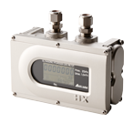
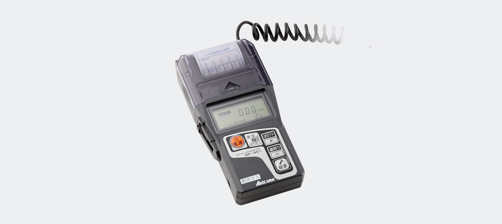
MP-401Digital Manometer
for Town Gas and LP Gas
Features
A digital manometer that realizes advanced test, measurement and management, furthermore, by simple operations as well as reliability in the field.
This meter is capable of performing an air-tight test and leak test for town and LP gases as well as pressure measurement by just one unit.
(Collaborative development product with Osaka Gas Co., Ltd.)
(Passed the self-imposed test conducted by the Japan L.P. Gas Instrument Inspection Association)
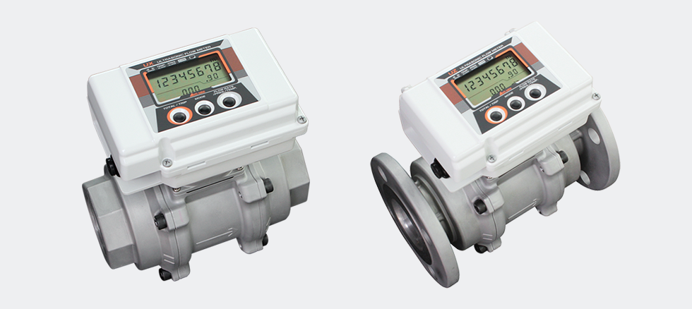
UX/UZUltrasonic Flow Meter
For Fuel Gas Control
Features
No straight pipe section required for installation
It is possible to connect the flow meter directly to a bend such as an elbow piece and a flexible pipe.
As wide as a 1:50 turn down ratio
Applicable also for measuring gas flow of a burner having a large turn down ratio.
Easy to replace batteries
Users can replace batteries without removing the meter from the piping.
Strong against dust, and high durability
Use the product in such a condition that does not allow the gas to re-liquefy into oil mist.
IP64 Protection – available for outdoor use
High temperature can cause the electronic circuit board to be deteriorated and batteries to be consumed. To avoid unnecessary rise in temperature, the product is recommended to be fitted with a sunshade.
Specifications
| Model | UX40 | UX50 | UZ40 | UZ50 | |
|---|---|---|---|---|---|
| Pipe connection | Screw | Flange | |||
| Rc1・1/2 (40A) | Rc2 (50A) | JIS10K 40A Flange (1・1/2″) | JIS10K 50A Flange (2″) | ||
| Maximum working pressure | 100kPa | 500kPa | |||
| Gas type ※1 | City gas (13A), butane (butane = 70%, propane = 30%), propane (propane = 98%, butane 2%), nitrogen and argon | ||||
| Power/ consumption | Battery ※2 | Exclusive lithium battery (life = 5 years @20℃ and 65%RH) | |||
| AC power | 100VAC±15%/max 10W (for 22mA) | ||||
| DC power | 24VDC±10%/max 2W (for 26.4V and 22mA) | ||||
| Flow range (Actual flow) | City gas, nitrogen and argon | 1.6~80m³/h | 3~150m³/h | 1.6~80m³/h | 3~150m³/h |
| Butane and propane | 3~80m³/h | 3~80m³/h | |||
| Accuracy ※3 | ±4%RD (for a range of 10% to 100% of the max flow) ±0.5%FS (for a range of 2% to 10% of the max flow) 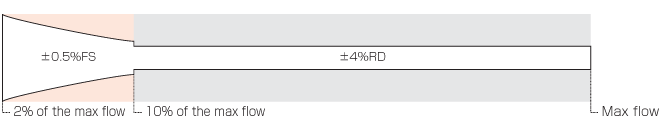 |
||||
| Temperature and pressure compensation ※4 | Yes/No (Normal/Standard conversion) | ||||
| Conversion accuracy | ±1.5%RD(@23℃ and 100kPa) | ±1.5%RD(@23℃ and 500kPa) | |||
| Display | Main display | Accumulated flow (actual flow: 8-digit integer + 2 decimal places, converted flow: 8-digit integer + one decimal place, accumulated flow of trip function) Alarm indication (for ultrasonic sensor, temperature sensor, pressure sensor, external memory and power voltage (for battery operation only)) |
|||
| Sub display | Instantaneous flow: 5 digits; temperature: 3 digits; and pressure: 5 digits | ||||
| Output | Analogue | (For 100VAC or 24VDC only) 4-20mADC (load resistance = max 400Ω): choose among options of instantaneous flow, temperature and pressure (default = instantaneous flow) | |||
| Pulse | Nch open-drain output (maximum load 24VDC, 50mA) Output 1 (accumulated flow volume pulse): standard = 1000L/P (choose 10, 100, 1000 or 10000 L/P): duty = 20 – 80% Output 2 (alarms): upper & lower Other Product In Group "รับจัดหาสินค้าอุตสาหกรรมและอะไหล่ทุกชนิด (15)"Contact Us
Copyright © mechatronics.co.th All Rights Reserved. | ||||