 Sign In


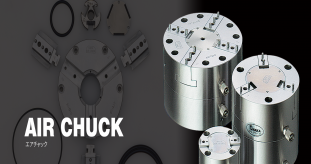


MicroCentric Air Chuck
Rotating Air Chucks

Rotating air chucks are ideal for precision turning and cylindrical grinding applications that require close concentricity, squareness, and parallelism tolerances. Variable clamping force enables clamping of thin-walled and other fragile parts with minimal distortion. All models, except the 3-50, feature a coolant or air passage through the center of the chuck.
Chuck Accuracy
- .00005" (0.0012mm) TIR is standard
- .00002" (0.0005mm) TIR is available
Stationary Air Chucks

Stationary air chucks are ideal for milling, drilling, tapping, and other applications requiring a compact self-contained workholding fixture. Air is supplied directly into the side of the chuck body, and the chuck can be mounted directly to the machine table or pallet. Through holes are available on all models.
Chuck Accuracy
- .00005" (0.0012mm) TIR is standard
- .00002" (0.0005mm) TIR is available
| 3-50NR12-3 | 3 in80 mm | 3 | .00005 in.0012 mm | .050 in1.3 mm | 920 lbs4.1 kN | 100 psi0.7 MPa | .475 in12 mm | 3.0 lb1.4 kg |
| 4-40NR19-3 | 4 in100 mm | 3 | .00005 in.0012 mm | .040 in1.0 mm | N/A | 100 psi7.0 kg/cm² | .750 in19.1 mm | 6 lb2.7 kg |
| 4-120NR19-3 | 4 in100 mm | 3 | .00005 in.0012 mm | .120 in3.0 mm | 1,485 lbs6.6 kN | 100 psi0.7 MPa | .750 in19.1 mm | 6.8 lb3.1 kg |
| 6-40NR-3 | 6 in150 mm | 3 | .00005 in.0012 mm | .040 in1.0 mm | N/A | 100 psi7.0 kg/cm² | 1.000 in25.4 mm | 14 lb6.4 kg |
| 6-40NR34-3 | 6 in150 mm | 3 | .00005 in.0012 mm | .040 in1.0 mm | N/A | 100 psi7.0 kg/cm² | 1.330 in33.8 mm | 13 lb5.7 kg |
| 6-120NR-3 | 6 in150 mm | 3 | .00005 in.0012 mm | .120 in3.0 mm | 3,820 lbs17.0 kN | 100 psi0.7 MPa | N/A | 15.9 lb7.0 kg |
| 6-120NR34-3 | 6 in150 mm | 3 | .00005 in.0012 mm | .120 in3.0 mm | 3,550 lbs15.8 kN | 100 psi0.7 MPa | 1.330 in33.8 mm | 15.4 lb7.0 kg |
| 8-120NR-3 | 8 in200 mm | 3 | .00005 in.0012 mm | .120 in3.0 mm | 6,570 lbs29.2 kN | 100 psi0.7 MPa | N/A | 42.2 lb19.1 kg |
| 8-120NR50-3 | 8 in200 mm | 3 | .00005 in.0012 mm | .120 in3.0 mm | 5,730 lbs25.2 kN | 100 psi0.7 MPa | 2.000 in50.8 mm | 40.5 lb18.4 kg |
| 10-220NR-3 | 10 in250 mm | 3 | .00005 in.0012 mm | .220 in5.6 mm | 10,330 lbs46.0 kN | 100 psi0.7 MPa | N/A | 75.2 lb34.1 kg |
| 10-220NR76-3 | 10 in250 mm | 3 | .00005 in.0012 mm | .220 in5.6 mm | 8,670 lbs38.6 kN | 100 psi0.7 MPa | 3.000 in76.2 mm | 69.0 lb31.3 kg |
Long Stroke Air Chucks

Long stroke air chucks feature extended jaw opening for load clearance or to clamp a range of diameters without changing top jaws. Long stroke chucks are available in rotating and stationary configurations. Their high accuracy makes them ideal for clamping headed workpieces for turning, grinding, or milling/drilling applications. Special models with total jaw stroke of .500" (12.7mm), .750" (19.1mm), and 1.000" (24.5mm) are also available. Please call for information.
Chuck Accuracy
- .00005" (0.0012mm) TIR is standard
- .00002" (0.0005mm) TIR is available
HST High Speed Air Chucks

HST High Speed Air Chucks feature a titanium chuck body and are actuated by a patented external wedge design that maintains clamping force at high spindle speeds without counterweights. This revolutionary design minimizes the effects of centrifugal force resulting in consistent clamping force throughout the chuck's rpm range.
HST chucks are available in standard, HS, and BP models. The HS models are dynamically balanced and feature MicroCentric's patented NR50 non-rotating air tube system. The NR50 design eliminates vibra tion caused by rotating air at higher spindle speeds, thus enhancing a machine's surface finish, and roundness capability.
Chuck Accuracy
- .0001" (0.0025mm) TIR is standard
- .00005" (0.0012mm) TIR is available
Sealed Air Chucks

Sealed air chucks feature a stainless steel cover that seals the jaw slides. This design prevents contamination from grit and swarf and minimizes chuck maintenance for high volume production operations. Sealed air chucks are available in rotating and stationary configurations and are ideal for cylindrical grinding operations as well as machining abrasive materials such as powdered metal, ceramic, or carbide.
QC precision located top jaw system is standard on sealed air chucks.
Chuck Accuracy
- .00005" (0.0012mm) TIR is standard
- .00002" (0.0005mm) TIR is available
Large Diameter Air Chucks

Large Diameter Air Chucks offer high accuracy and adjustable clamping force for machining large diameter precision and thin-walled workpieces. Large Diameter chucks are availalbe in three jaw as well as two and six jaw configurations. Large Diameter models with extended jaw stroke, air ports on OD of chuck body for stationary applications, and other special configurations are quoted upon request.
Chuck Accuracy
- .0002" (0.005mm) TIR is standard
- .0001" (0.0025mm) TIR is available
PPC110D Precision Power Chuck Models

- 4.33” (110mm) chuck diameter
- 3 jaw and 2 jaw models
- QC precision change jaw system and dowel pin located models
- Standard and long stroke models
- 1.063” (27mm) through hole
- Precision fit master jaws to minimize jaw lift
- Hardened chuck body, actuators, and master jaws, for long term accuracy and performance
- .0001” (0.0025mm) TIR
PPC300D106 Precision Power Chuck Models
Features
- 4.33” (110mm) chuck diameter
- 3 jaw and 2 jaw models
- QC precision change jaw system and dowel pin located models
- Standard and long stroke models
- 1.063” (27mm) through hole
- Precision fit master jaws to minimize jaw lift
- Hardened chuck body, actuators, and master jaws, for long term accuracy and performance
- .0001” (0.0025mm) TIR

Features
- 6.45” (165mm) chuck diameter
- 3 jaw and 2 jaw models
- QC precision change jaw system
- Standard and long stroke models
- 1.375” (35mm) through hole
- Precision fit master jaws to minimize jaw lift
- Hardened chuck body, actuators, and master jaws, for long term accuracy and performance
- .0001” (0.0025mm) TIR

Features
- 8.25” (210mm) chuck diameter
- 3 jaw and 2 jaw models
- QC precision change jaw system
- Standard and long stroke models
- 2.050” (52mm) through hole
- Precision fit master jaws to minimize jaw lift
- Hardened chuck body, actuators, and master jaws, for long term accuracy and performance
- .0001” (0.0025mm) TIR

Features
- 10.00” (250mm) chuck diameter
- 3 jaw and 2 jaw models
- QC precision change jaw system
- Standard and long stroke models
- 2.60” (66mm) through hole
- Precision fit master jaws to minimize jaw lift
- Hardened chuck body, actuators, and master jaws, for long term accuracy and performance
- .0002” (0.005mm) TIR

Features
- 12.00” (300mm) chuck diameter
- 3 jaw and 2 jaw models
- QC precision change jaw system
- Standard and long stroke models
- 4.17” (106mm) through hole
- Precision fit master jaws to minimize jaw lift
- Hardened chuck body, actuators, and master jaws, for long term accuracy and performance
- .0002” (0.005mm) T
Quick Change Chucks
-

The CB-NX series is a low profile dead length design with a reduced diameter nose for maximum tool clearance. The collet is coupled directly to the chuck body and remains fixed as the tapered seat moves forward when the chuck is actuated. The collet remains fixed in the Z axis during clamping and therefore does not create a pull back effect on the bar stock or workpiece.
CB-NX Features
- Low Profile Dead Length design
- Reduced diameter nose and short overall length provides increased tool clearance and maximum utilization of the machine's Z axis
- Radial adjusting screws to true-up tapered collet seat within .0002” (0.005mm)
- Lubricated-for-life design requires minimal maintenance
- All components hardened and precision ground for highest accuracy and long life
- Stop plates, stop housings, and ejectors can be mounted inside the chuck body for chucking applications
-

The ND series models are used for collet sizes 120mm and larger. The collet is coupled directly to the chuck body and remains fixed as the tapered seat moves forward when the chuck is actuated. Since the collet remains fixed in the Z axis during clamping it does not create a pull back effect on the bar stock or workpiece.
CB-ND Features- Dead Length design
- Radial adjusting screws to true-up the chuck assembly within .0002” (0.005mm)
- Lubricated-for-life design requires minimal maintenance
- All components hardened and precision ground for highest accuracy and long life
- Stop plates and stop housings can be mounted inside the chuck body for chucking applications requiring end stops or part ejectors
-

The NS series is a reduced diameter Dead Length design for sub spindles. Similar to ND chucks, the collet is coupled directly to the chuck body and remains fixed as the chuck is actuated. NS chucks also include a provision for mounting stops and ejectors inside the chuck body.
CB-NS Features- Small OD for maximum tool clearance on sub spindles.
- Dead Length design produces no pull back on the workpiece.
- Lubricated-for-life design requires minimal maintenance.
- All components hardened and precision ground for highest accuracy and long life.
- Stop plates and stop housings can be mounted inside the chuck body for applications requiring end stops or ejectors
- Spindle speeds up to 6,000 rpm
-

In the CB-NB series collet chucks, the collet is coupled directly to the draw tube connector. When the draw tube is actuated, the collet is drawn into the tapered seat of the chuck body, efficiently translating draw tube force into maximum clamping force.
CB-NB Features- Pull Back design maximizes the efficiency of the clamping system by concentrating all forces in the direction of the spindle for highest accuracy and greatest overall rigidity
- Low profile OD and short overall length provides increased tool clearance and maximum utilization of the machine's Z axis
- Radial adjusting screws to true-up the chuck assembly within .0002” (0.005mm)
- Lubricated for life design requires minimal maintenance
- All components hardened and precision ground for highest accuracy and long life
-

The CB-NDR is a patented Dead Length design for use with servo stop bar loaders. Unlike conventional dead length collet chucks, the NDR is actuated as the draw tube is drawn toward the machine spindle to prevent the bar from being pushed off the servo stop.
CB-NDR Features- Pull to Close Dead Length design produces no pull back and will not push the bar off the servo stop
- Radial adjusting screws to true-up the chuck assembly within .0002” (0.005mm)
- Lubricated-for-life design requires minimal maintenance
- All components hardened and precision ground for highest accuracy and long life
-

NK series chucks are a pull back design with the added flexibility of being able to mount end stops inside the chuck body for easy conversion from bar to chucking applications. The collet is coupled directly to the draw tube connector. As the draw tube is actuated the collet is drawn into the tapered seat efficiently translating draw tube force into maximum clamping force.
CB-NK Features- Pull Back design maximizes the efficiency of the clamping system by concentrating all forces in the direction of the spindle for highest accuracy and greatest overall rigidity
- Low profile OD and short overall length provides increased tool clearance and maximum utilization of the machine's Z axis
- Radial adjusting screws to true-up the chuck assembly within .0002” (0.005mm)
- Lubricated-for-life design requires minimal maintenance
- All components hardened and precision ground for highest accuracy and long life
- Removable stop plates and stop housings can be mounted inside the chuck body for chucking applications requiring end stops or part ejectors
-

The NRB series is a hydraulically actuated self-contained Pull Back design for non-rotating applications. The collet is coupled to the built-in piston and is drawn into the tapered seat when the chuck is actuated. Part stops can be mounted inside the chuck body.
CB-NRB Features- Self-contained design with built-in cylinder can be hydraulic or pneumatically operated
- Pull Back design maximizes the efficiency of the clamping system by concentrating the chucking force in the direction of the machine table, in addition to drawing the workpiece against the part stop
- Lubricated-for-life design requires minimal maintenance
- All components hardened and precision ground for highest accuracy and long life.
-

The CB-AG series collet chuck is a pull back design with a floating collet seat for machining shafts between centers. Centers or other part locators are mounted in the ID of the chuck. The floating collet seat can also be locked out to clamp parts on-center. Compact OD and short length compared to other compensating chuck designs provides greater rigidity.
CB-AG Features- 1.5mm (.060”) total compensation
- Mounting in ID of chuck body for mounting locating center
- Radial adjusting screws to true-up locating center within .0002” (0.005mm)
- Lubricated-for-life design requires minimal maintenance
- Compact design for greater rigidity
- Collet seat can be locked out for clamping parts on-center
- All components hardened and precision ground for highest accuracy and long life
-

Shafts can be machined complete between centers with MicroCentric's retractable collet chuck. A face driver mounted in the ID of the chuck drives the shaft as it is supported by the tailstock to turn the end of the shaft. When the chuck is actuated the collet moves forward to clamp the turned diameter enabling the OD of the shaft to be machined completed while the end of the shaft is securely clamped.
WSF Features
- Mounting for face driver in ID of chuck assembly
- Radial adjusting screws to true-up chuck assembly within .0002” (0.005mm)
- All components hardened and precision ground for highest accuracy and long life
MBS Diaphragm Chuck Models
-

Design
Self-contained design with built-in air cylinder. Air is supplied to the chuck by a multi passage air tube assembly with a rotary coupling. Coolant through the spindle capability is standard.
Application
OD and ID chucking for cylindrical grinding, turning, and hard turning. Ideal for workpieces requiring high concentricity, and/or close round ness. Ideal for fragile parts which are easily distorted, and applications requiring high spindle speeds. -

Design
Draw tube operated design. Can be actuated with either a hydraulic or pneumatic cylinder mounted at the rear of the machine spindle.
Application
OD and ID chucking for cylindrical grinding, turning, and hard turning. Ideal for workpieces requiring high concentricity, and applications requiring high chucking force and/or high spindle speeds. -

Design
Self-contained design with built-in air cylinder. Air ports are located on the side of the chuck body for stationary use.
Application
OD and ID chucking for milling, drilling, inspection, or any other non- rotating application requiring high concentricity and/or close workpiece roundness. The inherent spring characteristic of the diaphragm allows workpieces to be clamped without continuous air supply for pallet and tombstone applications.
MBS/N Stationary Diaphragm Chucks


Self-contained design with built-in air cylinder. Air ports are located on the side of the chuck body for stationary use.
Application
OD and ID chucking for milling, drilling, inspection, or any other non- rotating application requiring high concentricity and/or close workpiece roundness. The inherent spring characteristic of the diaphragm allows workpieces to be clamped without continuous air supply for pallet and tombstone applications.
MBS/Z Draw Bar Operated Diaphragm Chucks


Draw tube operated design. Can be actuated with either a hydraulic or pneumatic cylinder mounted at the rear of the machine spindle.
Application
OD and ID chucking for cylindrical grinding, turning, and hard turning. Ideal for workpieces requiring high concentricity, and applications requiring high chucking force and/or high spindle speeds.
MBS/L Air Operated Diaphragm Chucks


Self-contained design with built-in air cylinder. Air is supplied to the chuck by a multi passage air tube assembly with a rotary coupling. Coolant through the spindle capability is standard.
Application
OD and ID chucking for cylindrical grinding, turning, and hard turning. Ideal for workpieces requiring high concentricity, and/or close round ness. Ideal for fragile parts which are easily distorted, and applications requiring high spindle speeds.